Section 04 ENGINE (2-STROKE)
Subsection 04 (TOP END)
Apply Molykote 111 on threads of cylinder head
bolts no. 14.
Torque bolts to 20 N•m(15lbf•ft) as per following
sequence in the next illustration. Repeat the
torquing sequence by retightening to 40 N•m
(30 lbf•ft).
F12D08A
12
11
7
4
8
2
3
1
6
10
9
5
Cylinder Head Cover
717 and 787 RFI Engines
Install cylinder head cover no. 1.
Apply Loctite 243 (blue) below head of screws
no. 14.
Apply also Molykote 111 on threads of screws
no. 14.
Torque cylinder head screws no. 14 to 12 N•m
(106 lbf•in) as per following illustrated sequence.
Repeat the procedure, retightening all screws to
24 N•m(17lbf•ft).
F01D46A
10 8 2 4 6 12
113 1 59 7
TORQUING SEQUENCE
ADJUSTMENT
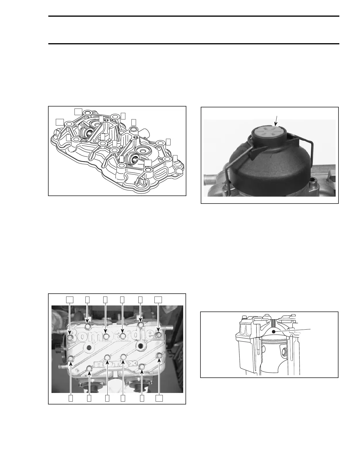
RAVE Valve
787 RFI Engines
Turn the red plastic knob no. 17 until it is flush to
the valve cover.
F00D0GA
1
1. Knob flush with the cover
Combustion Chamber Volume
Measurement
All Engines
NOTE: This procedure is required to determine
the thickness of the cylinder base gasket to be in-
stalled if a crank repair has involved replacement
of connecting rods or if you are experiencing
repetitive engine seizure.
The combustion chamber volume is the region in
the cylinder head above the piston at Top Dead
Center. It is measured with the cylinder head in-
stalledontheengine.
F01D5VA
1
1. Combustion chamber
NOTE: When checking the combustion chamber
volume, engine must be cold, piston must be free
of carbon deposit and cylinder head must be lev-
eled.
smr2004-Complete Line Up 125

 Loading...


