Section 04 ENGINE (2-STROKE)
Subsection 03 (MAGNETO SYSTEM)
DISASSEMBLY
717 Engines
NOTE: The magneto system can be disassembled
without removing the engine from the watercraft.
Magneto Cover
Remove screws no. 11 andwiresupportno. 12,
then withdraw magneto cover no. 1.
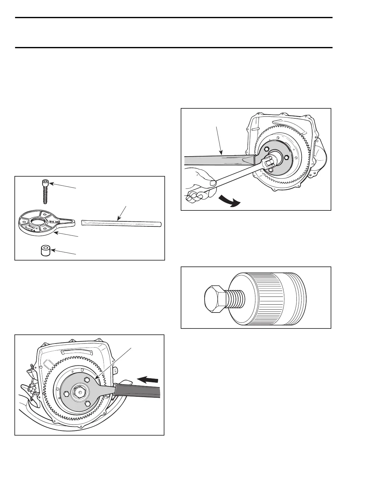
Magneto Flywheel and Ring Gear
Magneto flywheel no. 2 is locked with puller plate
(P/N 420 876 080), sleeves (P/N 290 847 220) and
extension handle (P/N 295 000 125).
F01D47A
2
3
4
1
1. Screw
2. Extension handle
3. Puller plate
4. Sleeve
Using three M8 x 35 screws (P/N 420 841 591), in-
stall screws through puller plate and slide sleeves
on screws then secure puller plate on magneto fly-
wheel so that sleeves are against ring gear no. 3.
Install extension handle on end of puller plate.
F01D48A
1
TYPICAL
1. Sleeves on opposite side
Using a suitable socket, unscrew retaining nut
no. 13 COUNTERCLOCKWISE when facing it.
NOTE: If socket is found too large to be inserted in
puller plate, machine or grind its outside diameter
as necessary.
F01D4BA
1
TYPICAL
1. Extension handle locking crankshaft
Remove nut no. 13 and lock washer no. 14 from
magneto flywheel.
Magneto flywheel is easily freed from crankshaft
with puller (P/N 529 035 547).
A00C1AA
Fully thread on puller in puller plate.
Tighten puller bolt and at the same time, tap on
bolt head using a hammer to release magneto fly-
wheel from its taper.
86 smr2004-Complete Line Up

 Loading...


