Section 18 WIRING DIAGRAM
Subsection 01 (WIRING DIAGRAMS)
A32E3ZA
1
2
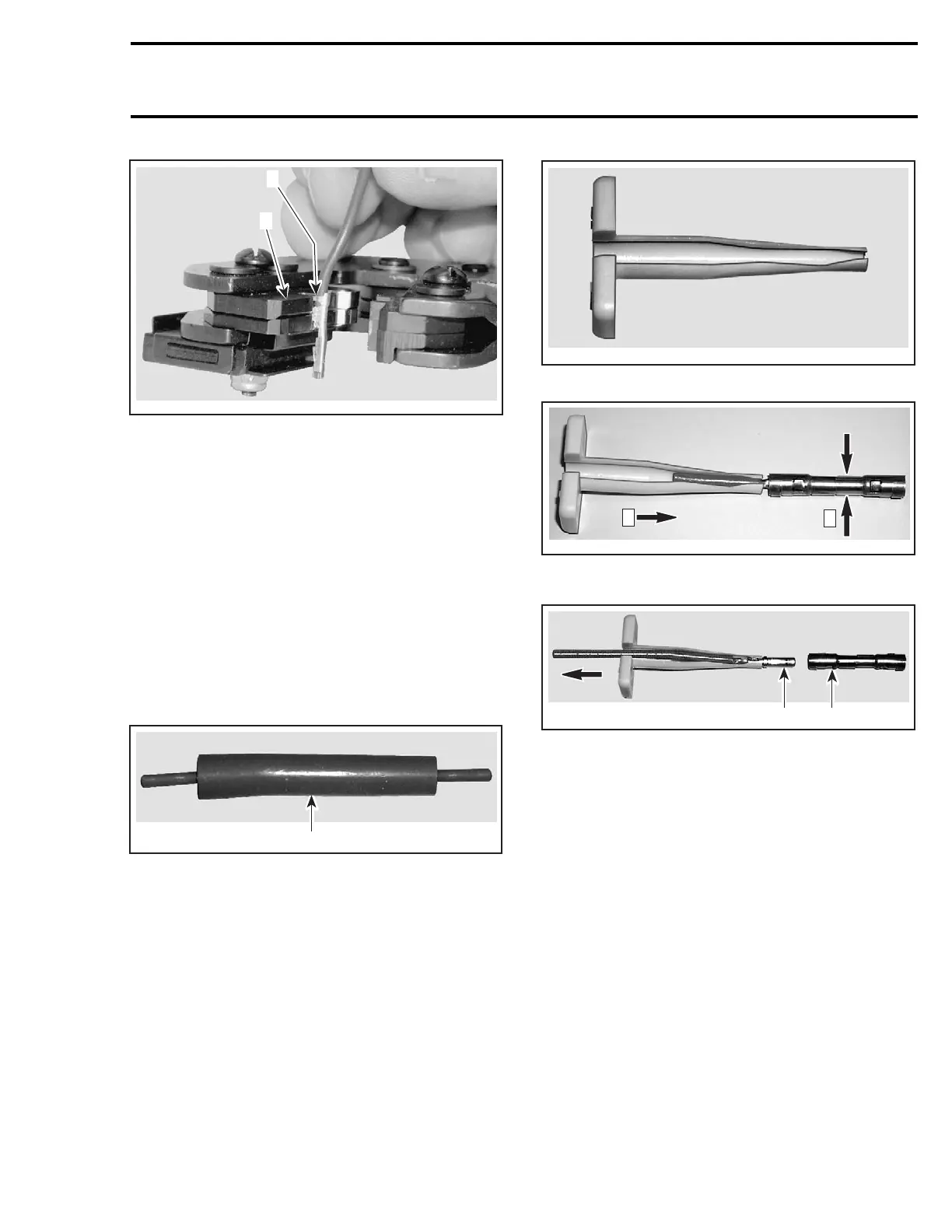
1. Top of terminal tabs
2. Aligntabswithpliersedge
Crimp terminal. Ensure no tiny wire goes out of
terminal. This might cause strange problems of
the electrical system.
Lubrication
Do not apply any product to the pins of the con-
nector on the ECM.
MAIN FUSE HOLDER JOINT
CONNECTOR
DI Models
The fuse holder is located in the rear electrical box.
1
F12H0ZA
1. Main fuse holder joint connector
NOTE: In the following illustrations, the joint insu-
lator has been removed for clarity purpose only. It
is not necessary to remove it to separate the joint.
The same procedure is to be used each side of the
joint.
Insert the Deutsch joint connector tool (no.
114010) on the wire and push tool toward the
joint to release it. While holding the joint insulator,
push the tool until it bottoms. It is now unlocked.
Maintaining the pressure with the tool, pull the
wire out.
F12H10A
DEUTSCH JOINT CONNECTOR TOOL (NO. 114010)
F12H11A
1
2
Step 1: Hold the insulator
Step 2: Push the tool until it bottoms
1
F12H12A
2
1. While holding tool pressure, pull wire until terminal releases
2. Joint connector
For installation, simply push the wire in the con-
nector. You should hear a locking “click”.Tryto
pull the wire out to ensure terminal is properly
locked. If not, remove the wire and bend the tabs
inside the joint connector to allow proper locking.
Recheck.
smr2004-Complete Line Up 797

 Loading...


