Section 14 STEERING SYSTEM
Subsection 01 (STEERING SYSTEM)
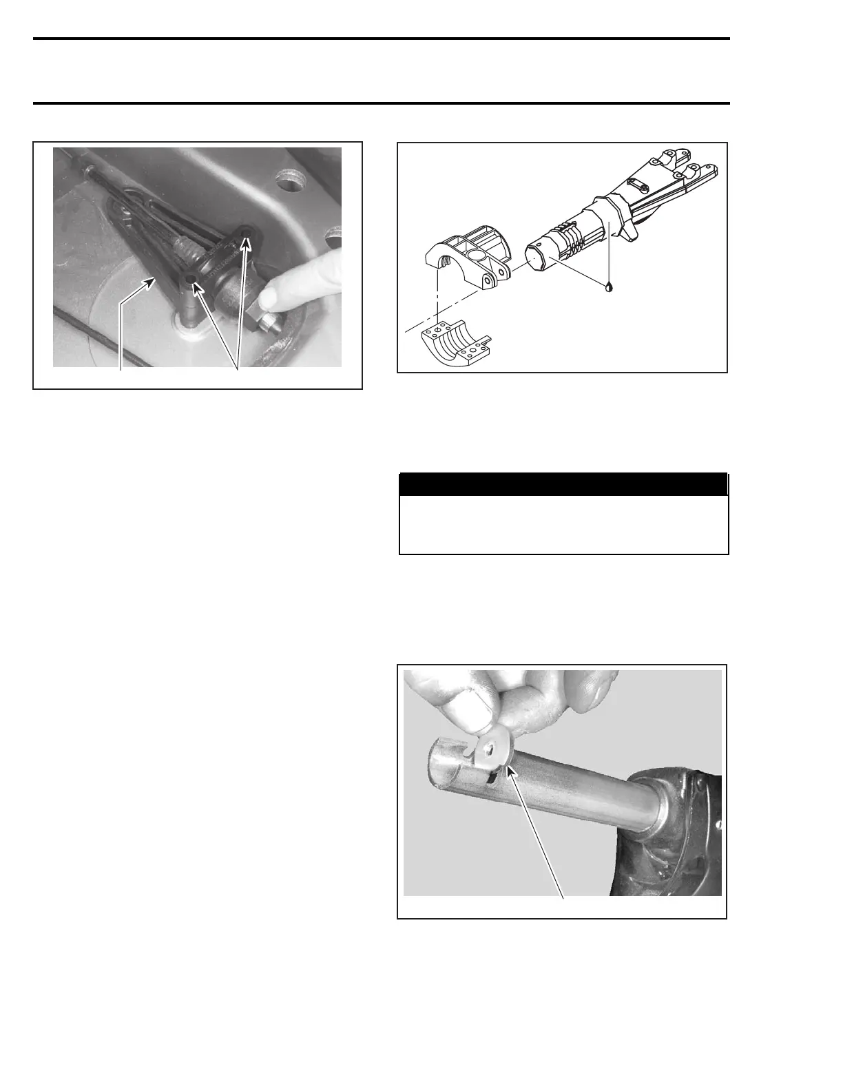
1
F08K0KA
2
1. Cable support
2. Remove M6 bolts
Disconnect ball joint no. 21 of steering cable from
jet pump nozzle.
Remove ball joint no. 21,jamnutno. 22 and boot
no. 23.
Loosen nut no. 25 and remove half rings no. 26
and O-ring no. 27.
NOTE: To loosen nut, use steering cable tool
(P/N 295 000 145).
Remove steering cable from watercraft.
ASSEMBLY
Assembly is essentially the reverse of disassem-
bly procedure. However, pay particular attention
to the following.
Lever
Prior installing lever no. 10, apply synthetic grease
to pivot.
Steering Stem
Apply synthetic grease to front and rear thrust
bearing surface.
1
F08K0MA
1. Apply synthetic grease
Steering Stem Arm and Support
Position steering stem arm no. 15 and support
no. 16 onto steering stem no. 14.
WARNING
Make sure integrated flat keys of steering
stem arm and support are properly seated in
steering stem keyways.
Handle Grip and Grip Insert
When installing the grip insert no. 5 in the handle-
bar no. 24, ensure that it is properly inserted in the
slot at the end of the handlebar tubing.
F02K0JA
1
1. Grip insert
Install grip no. 1 on handlebar no. 22 matching it
to the notch in the handlebar.
Install flat washer no. 4 and screw no. 3.
700 smr2004-Complete Line Up

 Loading...


