Section 06 ENGINE MANAGEMENT (RFI)
Subsection 03 (COMPONENT INSPECTION )
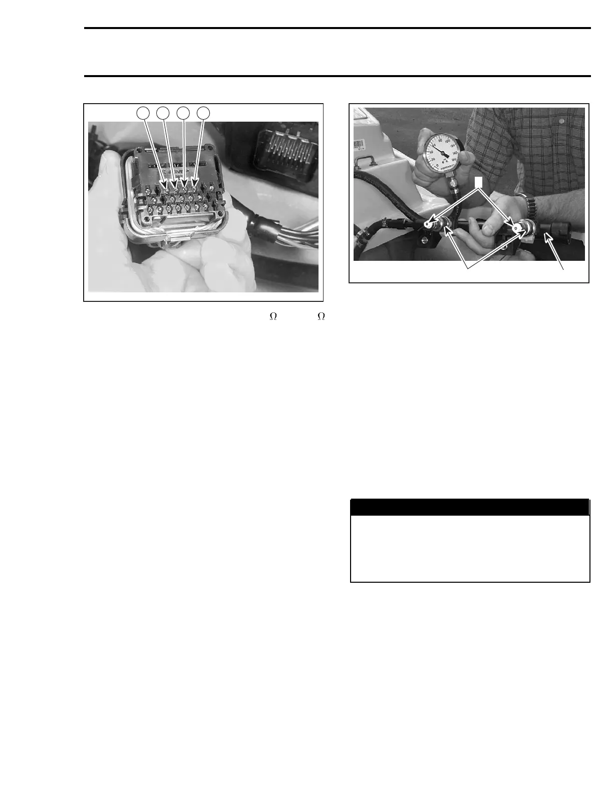
F07F15A
18 19 20 21
The resistance should be between 2.3 and 2.5
at temperature of 20°C(68°F).
If resistance value is incorrect, check wiring har-
ness between AMP plug connector and fuel injec-
tors for damaged wires or bad connections. Re-
pair if necessary.
Recheck resistance value at AMP plug connector
#4.
If not within specification, replace the fuel injector.
Leakage Test (fuel injectors)
To perform a leakage test, the injectors and fu-
el rail have to be removed from engine. See RE-
MOVAL in this subsection for the procedure.
NOTE: Do not detach injectors from fuel rail.
Reconnect the wire connector of the injector.
Place each injector in a clean bowl.
Install the safety lanyard cap on the switch to ac-
tivate the fuel pump.
Check for fuel leakage from the injector nozzle.
There should be less than 1 drop of fuel per
minute.
2
1
F07F16A
3
1. Fuel injectors
2. Fuel rail
3. Injector nozzles
If not within specification, replace the fuel injec-
tor(s).
LEAK TEST (SUPPLY AND
VENTILATION CIRCUITS)
Refer to FUEL SYSTEM.
HIGH PRESSURE TEST (FUEL
PUMP CIRCUIT)
Before proceeding to the pressure test ensure the
battery is fully charged. Battery voltage must be
over 12 volts.
WARNING
The fuel hose may be under pressure. Cov-
er the fuel line connection with an absorbent
shop rag. Slowly disconnect the fuel hose
toreleasethepressure. Wipeoffanyfuel
spillage inside bilge.
Press on both tabs and pull quick connect fitting
to disconnect the fuel hose from fuel rail.
smr2004-Complete Line Up 311

 Loading...


