Section 14 STEERING SYSTEM
Subsection 01 (STEERING SYSTEM)
VALVE
GTX 4-TEC Series
Disassembly
Remove O.P.A.S. “U” lever screw no. 2,flat
washer no. 3, bushing no. 4 and venturi bushing
no. 5 from nozzle.
Remove jet pump, filter and formed hose no. 32
(refer PROPULSION SYSTEM).
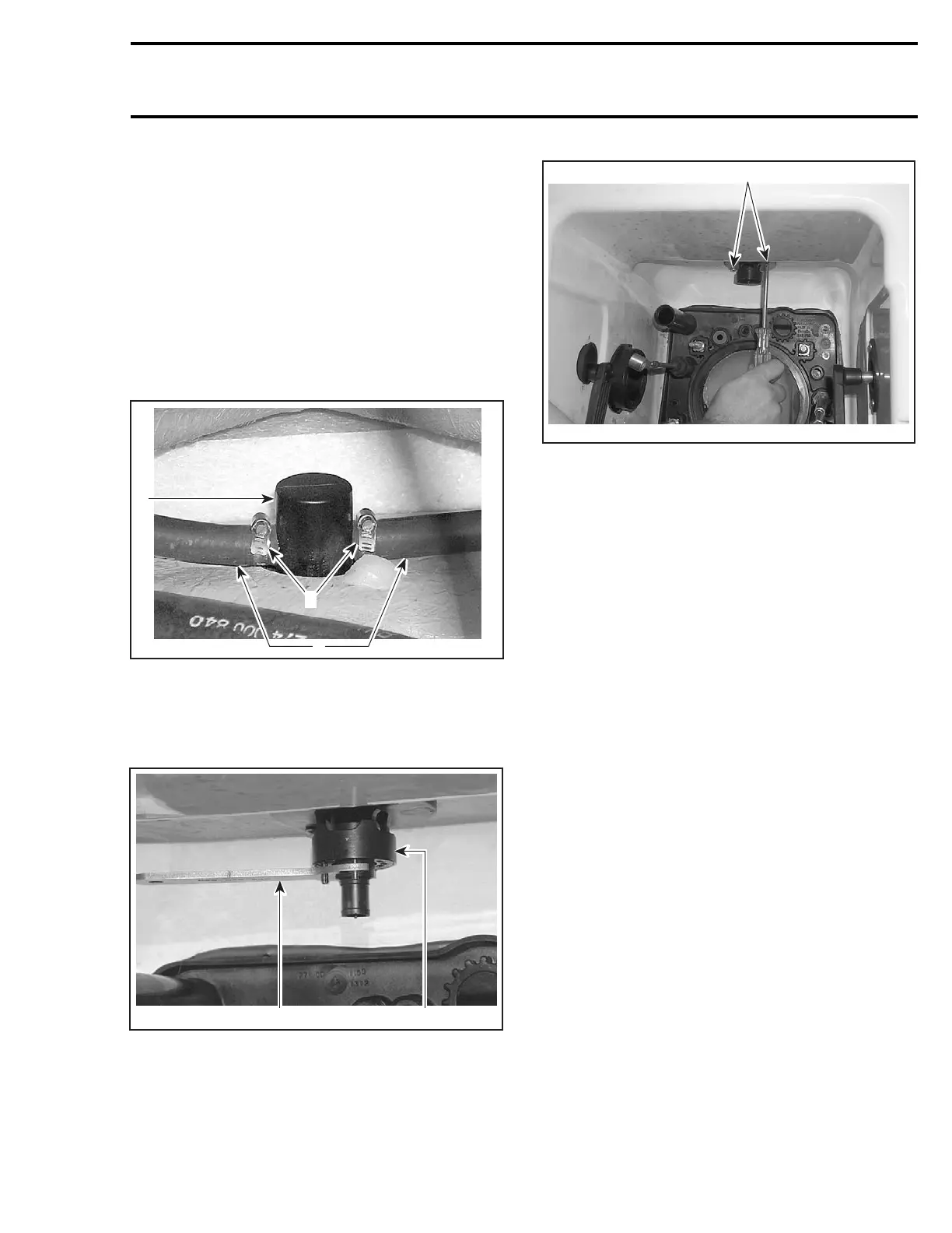
Remove gear clamps no. 35 to remove water
hoses no. 26 from valve.
F18K0UA
3
2
1
1. Gear clamps
2. Valve
3. Water hoses
Unscrew bottom nut of valve no. 33 using
O.P.A.S. cylinder nut wrench (P/N 529 035 840).
1
F18K0VA
2
1. O.P.A.S. cylinder nut wrench
2. Valve
Remove 2 Phillips screws no. 34 from valve collar.
1
F18K0WA
TYPICAL
1. Phillips screws
Remove valve downwards from pump tunnel.
Assembly
Assembly is the reverse process of disassembly,
make sure of the following when doing assembly:
– Check for cracks on formed hose no. 32,
change if necessary.
– Make sure the valve is installed in the right po-
sition.
Torque Phillips screws no. 34 to 2.2 N•m
(19 lbf•in).
Tighten gear clamps no. 31 manually to 1.7 N•m
(15 lbf•in).
WATER HOSE
GTX 4-TEC Series
Disassembly
Removal procedure for RH and LH water hose is
same.
Remove side vane and cylinder support assembly
as mentioned above.
Remove gear clamps no. 35 to remove water
hose no. 26 from valve.
Pulloutthewaterhoseno. 26 from exterior.
smr2004-Complete Line Up 707

 Loading...


