Section 08 ENGINE MANAGEMENT (4-TEC)
Subsection 02 (COMPONENT INSPECTION AND ADJUSTMENT)
Connect one test probe to the WHITE/GREY wire
and the other test probe to the switch top termi-
nal. Measure resistance, it must be close to 0
ohm.
Connect one test probe to the BLACK wire and
the other test probe to the switch ring. Measure
resistance, it must be close to 0 ohm.
Safety Lanyard on Switch
Connect test probes to switch BLACK and
BLACK/YELLOW wires. Measure resistance,
it must be close to 0 ohm.
SPARK PLUGS
Disassembly
WARNING
Never remove ignition coil from the spark
plug without disconnecting it from the wiring
harness. Flammable vapors may be present
inthebilgeandignitedbyasparkwhich
could cause an explosion.
Disconnect the wiring harness from the ignition
coil.
Remove the ignition coil.
First unscrew the spark plug one turn.
Clean the spark plug and cylinder head with pres-
surize air then completely unscrew.
Spark Plug Installation
Prior to installation make sure that contact sur-
faces of the cylinder head and spark plug are free
of grime.
1) Using a wire feeler gauge, set electrode gap
according to the following chart.
2) Apply anti-seize lubricant over the spark plug
threads to prevent possible seizure.
3) Hand screw spark plug into cylinder head.
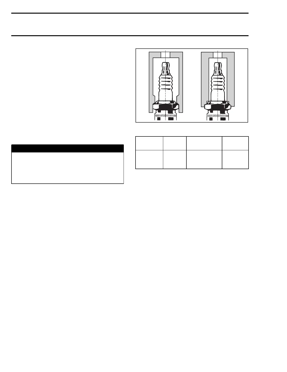
Then, tighten the spark plug clockwise an
additional 1/4 turn with a proper socket.
A00E0BA
2
1
1. Proper socket
2. Improper socket
ENGINE
SPARK
PLUG
TORQUE
GAP
MM (IN)
All 4-TEC
NGK
DCPR8E
Hand tighten
+ 1/4 turn with
asocket
0.75 (.030)
CRANKING SYSTEM
See above for start/stop switch and the DESS post
testing. Refer to STARTING SYSTEM section for
other tests.
438 smr2004-Complete Line Up

 Loading...


