Section 06 ENGINE MANAGEMENT (RFI)
Subsection 03 (COMPONENT INSPECTION )
2
F02F1XA
1
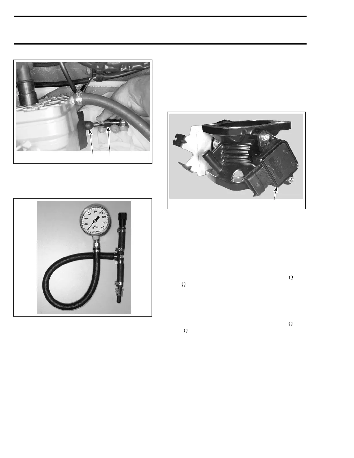
1. Quick connect fitting
2. Fuel rail
Install fuel pressure gauge (P/N 529 035 591) be-
tween fuel rail and fuel hose from fuel tank.
F02B0BA
FUEL PRESSURE GAUGE (P/N 529 035 591)
Install the safety lanyard cap on the switch to ac-
tivate the fuel pump.
The fuel pump should run for approximately 1 sec-
ond and the fuel pressure should be between 386 -
414 kPa (56 - 60 PSI).
Check hose connections at fuel pump and at fuel
rail.
ELECTRONIC MANAGEMENT
THROTTLE POSITION SENSOR
(TPS)
Check the resistance value of the throttle position
sensor.
F07F0EA
1
TYPICAL
1. Throttle position sensor (TPS)
Disconnect the AMP plug connector #4 on the
MPEM.
Using a multimeter, check the resistance between
terminal 3 (PURPLE/BROWN wire) and terminal 4
(BLACK/BROWN wire) on the AMP plug connec-
tor.
The resistance should be between 1.6 k and
2.4 k
.
Check also the resistance between terminal 4
(BLACK/BROWN wire) and terminal 11 (WHITE/
BROWN wire) with the throttle plate in idle posi-
tion.
The resistance should be between 710
and
1380
.
312 smr2004-Complete Line Up

 Loading...


