Section12ELECTRICALSYSTEM
Subsection 04 (INSTRUMENTS AND ACCESSORIES)
• check engine (CHK ENG)
• sensor failure (vehicle electronic equipment)
(SENSOR)
• invalid safety lanyard (KEY)
• safety lanyard, learning key active (L KEY)
• end of faults (END).
A beeper will sound depending on the fault occur-
ring to catch the driver attention when necessary.
Except for low liquid levels, which can be correct-
ed by refilling, it is recommended to see an autho-
rized Sea-Doo dealer when other messages occur.
NOTE: If a fault occurs, this system generates
numbered fault codes (P-XXXX) that can be dis-
played through the information center using a spe-
cial procedure. In case of a failure, refer to DI-
AGNOSTIC PROCEDURES in ENGINE MANAGE-
MENT.
Warning Light
The red warning LED (Light-Emitting Diode) blinks
along with the beeper to catch your attention.
Maintenance Information
When the watercraft is due for a maintenance in-
spection, the message MAINT will blink. After-
wards, it will blink at every start-up for 10 seconds.
After servicing, ensure to clear it.
ADDITION OF ELECTRICAL
ACCESSORIES
4-TEC Models
Every time an electrical accessory is added such
as an electric bilge pump or a VTS for instance, it
must be registered using B.U.D.S. to activate it in
the MPEM.
If an option is installed but not checked in
B.U.D.S., the information center will not display
that option. If an option is checked in B.U.D.S.
but not installed in vehicle, a fault code will be
generated.
Use the OPTIONS area in the Setting tab in
B.U.D.S.
INSPECTION
Information Center
GTILERFIandXPDIModels
The PURPLE wire is the 12 Vdc power source of
the Information Center.
The BLACK wire is the ground.
The accuracy of some features of the Information
Center can be checked with a potentiometer as
follows.
Fuel Level
Disconnect the AMP connector #1 from the
MPEM.
Using an appropriate terminal remover, remove
the PINK wire from the AMP connector.
Reconnect the connector housing.
Disconnect the 2-circuit connector housing from
the information center which contains a PURPLE
and BLACK wires.
Remove the BLACK wire from the receptacle
housing.
Reconnect the connector housing and the BLACK
terminals together.
Connect potentiometer test probes to the PINK
and BLACK wires.
Adjust potentiometer to the resistance values as
per following chart to test the accuracy of the In-
formation Center.
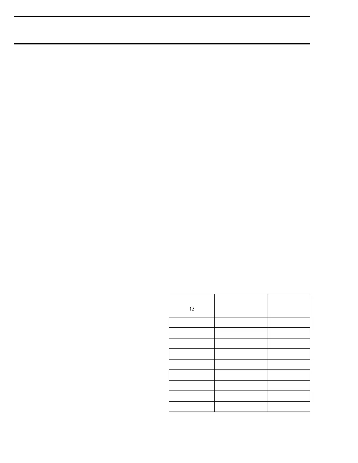
RESISTANCE
(
)
DISPLAYED
SEGMENT ON
FUEL LEVEL LCD
LOW FUEL
LEVEL RED
LIGHT
4.8 + 2.2 FULL
OFF
17.8 ± 2.2 7/8
OFF
27.8 ± 2.2 6/8
OFF
37.8 ± 2.2 5/8
OFF
47.8 ± 2.2 4/8
OFF
57.8 ± 2.4 3/8
OFF
67.8 ± 2.8 2/8
OFF
77.8 ± 3.6 1/8
ON
89.8 ± 3.6 EMPTY
ON
600 smr2004-Complete Line Up

 Loading...


