Section 06 ENGINE MANAGEMENT (RFI)
Subsection 03 (COMPONENT INSPECTION )
Also remember this validates the operation of the
sensor at ambient temperature. It does not val-
idate the over temperature functionality. To test
it, the sensor could be removed from the engine/
muffler and heated with a heat gun while it is still
connected to the harness to see if the MPEM will
detect the high temperature condition and gener-
ate a fault code.
When working with injectors, the resistance value
might test good while the complete current would
notflowthroughthewirewhenpulsatingcurrent
is supplied to the injector in its normal operation.
A solution would be to use a jumper wire to direct-
ly supply the injector from the MPEM. If it now
works, replace the defective wire. A Noid light
(available from after-market tool/equipment sup-
pliers) may also be used to validate the injector
operation.
AIR INDUCTION SYSTEM
THROTTLE BODY
Check that the throttle plate moves freely and
smoothly when depressing throttle lever.
FUEL DELIVERY
FUEL FILTER
To inspect the fuel filter, the fuel pump assembly
has to be removed from the fuel tank. See RE-
MOVAL in this subsection for the procedure.
FUEL PUMP
The fuel pump operation can be checked as fol-
lows.
Install the safety lanyard cap on the switch. The
fuel pump should run for approximately 1 second
and then shut off.
If not, check the electrical circuit and the 10 A fuse
on the MPEM module.
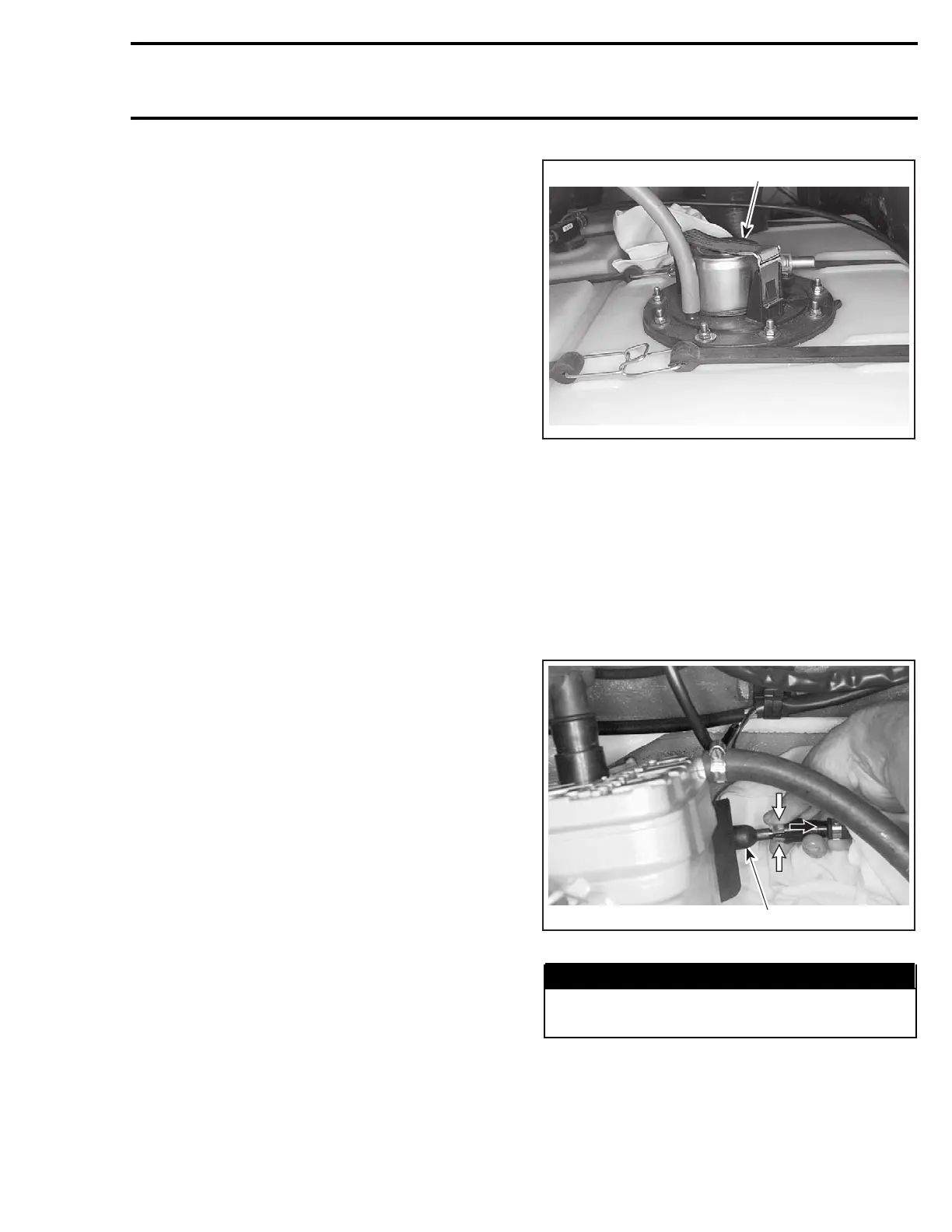
REGULATOR
The regulator is mounted on top of the fuel pump
assembly.
1
F07F0DA
1. Regulator
To inspect the regulator, a fuel pressure test must
be done.
Check that battery voltage is above 12 volts.
Place a suitable container below the quick connect
fitting of the fuel rail.
Cover the quick connect fitting with a shop towel.
Press on both tabs and disconnect the quick con-
nect fitting.
F07F11A
1
1. Fuel rail
WARNING
Fuel is under pressure. Wipe off any fuel
spillage in the bilge.
smr2004-Complete Line Up 309

 Loading...


