Section 06 ENGINE MANAGEMENT (RFI)
Subsection 03 (COMPONENT INSPECTION )
WARNING
All electrical actuators (injectors, fuel pump,
RAVE solenoid, ignition coil and starter sole-
noid) are permanently connected to the bat-
tery positive terminal, even when the safety
lanyard is removed. Always disconnect the
battery prior to disconnecting any electric or
electronic parts.
To perform verifications, a good quality multimeter
such as Fluke 111 (P/N 529 035 868) should be
used.
Pay particular attention to ensure that pins are
not out of their connectors or out of shape. The
troubleshooting procedures cover problems not
resulting from one of these causes.
WARNING
Ensure all terminals are properly crimped on
wires and connector housings are properly
fastened.
Before replacing a MPEM, always check electri-
cal connections. Make sure that they are very
tight and they make good contact and that they
are corrosion- free. A “defective module” could
possibly be repaired simply by unplugging and
replugging the MPEM. The voltage and current
might be too weak to go through dirty wire pins.
Check carefully if posts show signs of moisture,
corrosion or if they look dull. Clean pins properly
andthencoatthemwithsilicon-baseddielectric
grease or other appropriate lubricant (except if
otherwise specified) when reassembling them. If
the newly replaced MPEM is working, try the old
one and recheck if it works.
NOTE: Ensure that all electronic components
are genuine -- particularly in the ignition system.
Installing resistive caps, non-resistive spark plug
cables (or modified length) or non-resistive spark
plugs may lead to generate fault codes or bad
operation.
NOTE: Use the VCK to diagnose fault codes. See
TROUBLESHOOTING section.
After a problem has been solved, ensure to clear
the fault(s) in the MPEM using the VCK. Refer to
DIAGNOSTIC PROCEDURES.
Resistance Measurement
Whenmeasuringtheresistancewithanohmme-
ter, all values are given for a temperature of 20°C
(69°F). The resistance value of a resistance varies
with the temperature. The resistance value for
usual resistor or windings (such as injectors) in-
creases as the temperature increases. However,
our temperature sensors are NTC types (Negative
Temperature Coefficient) and work the opposite
which means that the resistance value decreases
as the temperature increases. Take it into account
when measuring at temperatures different from
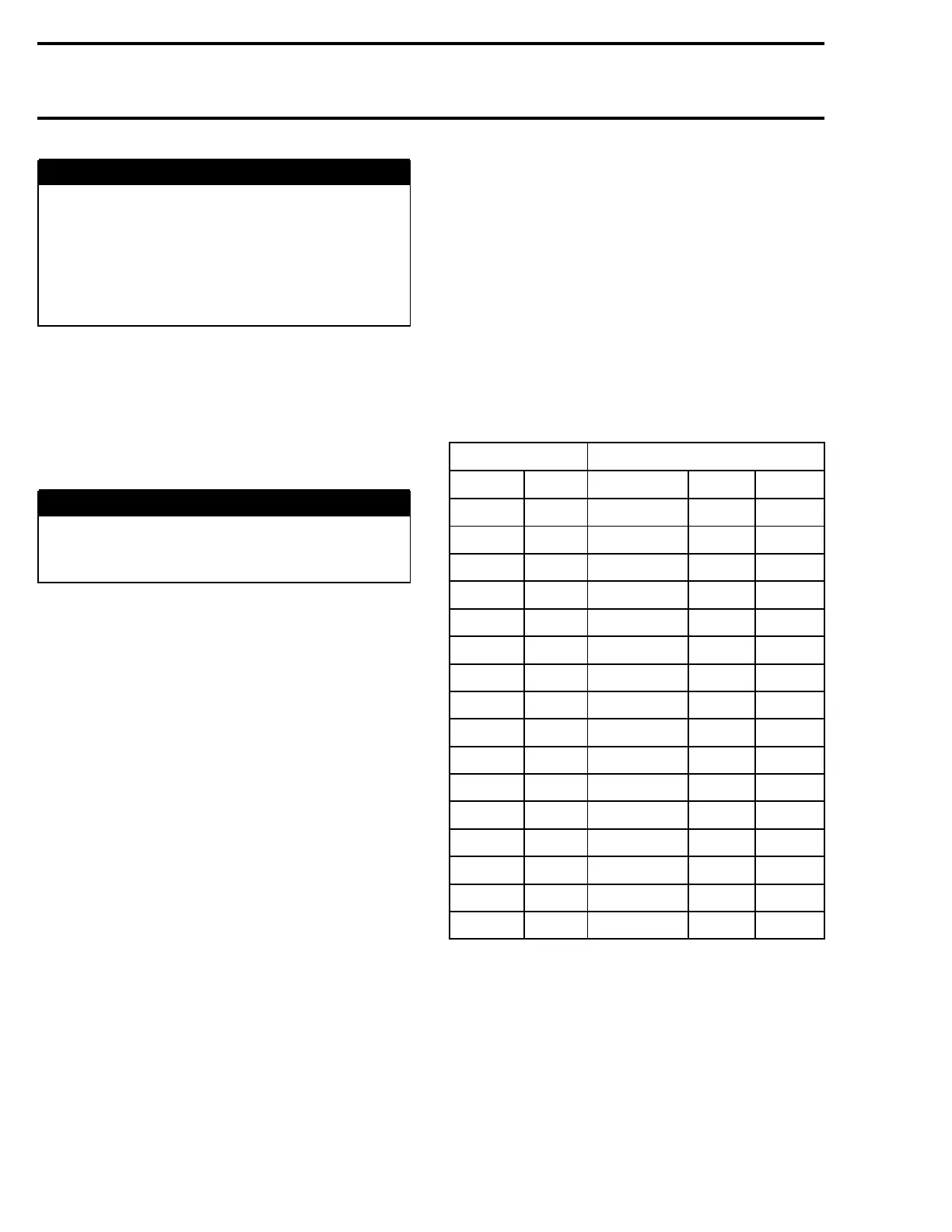
20°C(69°F). Use this table for resistance variation
relative to temperature for temperature sensors.
TEMPERATURE RESISTANCE (OHMS)
°C °F NOMINAL LOW HIGH
-30 -22 12600 11800 13400
-20
-4
11400 11000 11800
-10
14
9500 8000 11000
0 32 5900 4900 6900
10 50 3800 3100 4500
20 68 2500 2200 2800
30 86 1700 1500 1900
40 104 1200 1080 1320
50 122 840 750 930
60 140 630 510 750
70 158 440 370 510
80 176 325 280 370
90 194 245 210 280
100 212 195 160 210
110 230
145
125 160
120 248
115
100 125
CONVERSION CHART FOR TEMPERATURE SENSORS
The res
istance value of a temperature sensor may
tes
tgoodatacertaintemperaturebutitmightbe
d
efective at other temperatures. If in doubt, try a
new sensor.
308 smr2004-Complete Line Up

 Loading...


