Section 14 STEERING SYSTEM
Subsection 01 (STEERING SYSTEM)
DISASSEMBLY
NOTE: See farther in this document for proce-
dures pertaining to XP DI models.
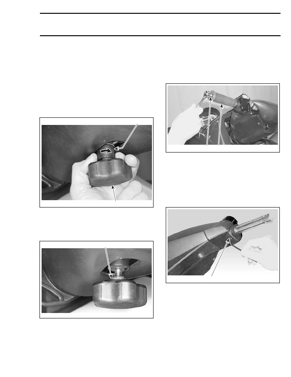
Adjustment Handle
GTX 4-TEC Supercharged Limited Models Only
Set handlebar to its lowest position by turning ad-
justment handle no. 30 counterclockwise.
While holding adjustment handle no. 30,turnsup-
port bushing no. 31 clockwise.
2
1
F07K0MA
TYPICAL
1. Adjustment handle
2. Support bushing
Hold jam nut no. 34 and unscrew adjustment han-
dle no. 30 from adjuster screw no. 29.
1
F07K0NA
TYPICAL
1. Loosen jam nut
Handle Grip and Grip Insert
To remove handle grip no. 1, pull out cap no. 2 and
remove screw no. 3.
Pull out grip and remove grip insert from handlebar
no. 22.
1
F18K0AA
2
1. Handle grip
2. Remove screw
NOTE: Verify grip insert for damage.
Steering Cover
Remove grips no. 1.
Loosen set screws no. 5 of handlebar housings
no. 6 and no. 41.
1
F18K0BA
GTX4-TECSERIESANDRXP4-TEC
1. Set screw
smr2004-Complete Line Up 687

 Loading...


