Section13PROPULSION
Subsection 04 (VARIABLE TRIM SYSTEM)
F01J2GA
Tighten nuts no. 11 to 7 N•m(62lbf•in).
Connect wires of motor.
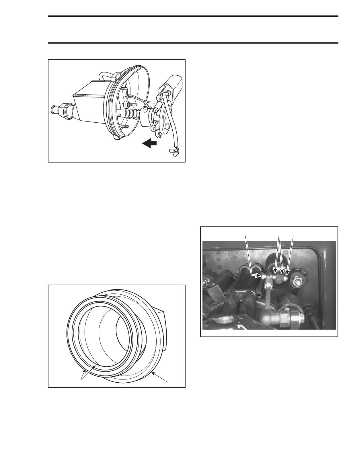
CAUTION: Make sure wire color codes match.
Install cover no. 7.
NOTE: Make sure seal no. 12 is in place.
INSTALLATION
Installation is essentially the reverse of removal
procedures. However pay particular attention to
the following.
Nut and Sealing Washer
Place sealing washer no. 5 on nut no. 4. Make
sure seal lips are facing toward hull.
F01J2LA
1
2
1. Seal lips facing hull
2. Nut
Apply Loctite Primer N (P/N 293 800 041) to
threads of VTS housing, and to nut no. 4.
Apply Loctite 243 (blue) to nut no. 4.
Install nut with sealing washer and torque to
7N•m(62lbf•in) using the VTS socket tool
(P/N 295 000 133).
Apply synthetic grease to sliding shaft.
Boot and Clamps
Install rubber boot no. 3 over sliding shaft and se-
cure with clamps.
VTS Rod
Install rubber boot no. 3, over sliding shaft and
secure with clamps.
RXP Models
Secure the VTS rod onto the sliding shaft end us-
ing bolt no. 13 and nut no. 14. Torque nut to
7N•m(62lbf•in).
XP DI Models
Install ball joint on LEFT side of sliding shaft no. 10
using bolt no. 13, washers no. 15 and nut no. 14.
Torquenutto10N•m(88lbf•in).
F06J01C
2 13
TYPICAL
1. Washers
2. Bolt
3. Lock nut
ADJUSTMENT
RXP Models
No adjustment is required.
smr2004-Complete Line Up 683

 Loading...


