Section 05 ENGINE (4-TEC)
Subsection 03 (EXHAUST SYSTEM)
Inspect plane surfaces for warpage. Small defor-
mation can be corrected by grinding surface with
a fine sand paper. Install sand paper on a surface
plate and rub part against oiled sand paper.
Clean all metal components in a solvent.
Installation
Installation is essentially the reverse of removal
procedures. However, pay particular attention to
the following.
NOTE: There is no gasket between engine block
and exhaust manifold.
Apply Loctite 518 on threads of screws.
To help holding the manifold while installing
screws, first insert the exhaust manifold into the
exhaust pipe no. 1 then, install the upper front
screw. Continue with the remaining screws.
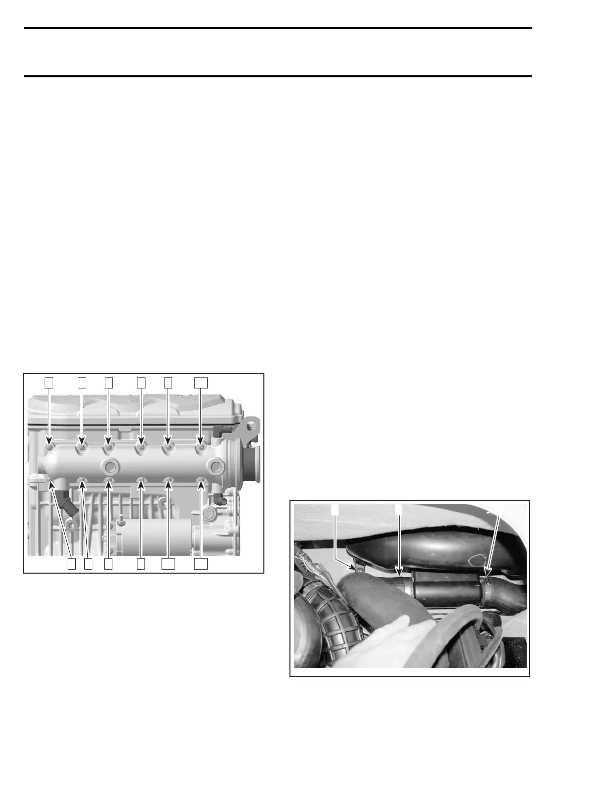
Torque screws to10 N•m(88lbf•in) as per follow-
ing illustrated sequence. Repeat the procedure,
torquing screws again to10 N•m(88lbf•in).
R1503motr152A
7 5 1 3 9 11
8 6 4 2 10 12
CAUTION: Never run engine without supplying
water to the exhaust cooling system when wa-
tercraft is out of water.
After installation, ensure there is no coolant or ex-
haust gas leak when the engine is running. Test
run the engine while supplying water to the flush-
ing connector.
MUFFLER
Removal
Remove the exhaust pipe no. 1. See above.
Disconnect the temperature sensor connector.
Disconnect the outlet hose no. 5.
Inspection
Inspect parts condition paying attention for cracks
or other damage. Check hoses. Replace any de-
fective part.
Installation
Installation is the reverse of the removal proce-
dures.
After installation, ensure there is no coolant or ex-
haust gas leak when the engine is running. Test
run the engine while supplying water to the flush-
ing connector.
RESONATOR
Removal
RXP 4-TEC Models
Remove supercharger inlet hose.
Disconnect speed sensor connector.
Remove VTS. Refer to VARIABLE TRIM SYSTEM.
All 4-TEC Models
Disconnect inlet hose no. 5.
Unscrew retaining screw no. 12.
Disconnect outlet hose no. 13. from resonator.
All 4-TEC Models
F19D03A
312
1. Inlet hose
2. Retaining screw
3. Outlet hose
Carefully pull out the resonator no. 9.
214 smr2004-Complete Line Up

 Loading...


