Section12ELECTRICALSYSTEM
Subsection 02 (CHARGING SYSTEM)
– Set multimeter to Vac scale.
– Start and rev engine to 3500 RPM. The obtained
value should be between 45 and 70 Vac, and
25 Vac on 4-TEC engines.
– If the stator is out of specification, replace it.
Stator
787 RFI Engines
STATIC TEST: CONTINUITY
– Disconnect the magneto wiring harness con-
nector.
– Install the 4-pin magneto harness adapter
(P/N 295 000 131).
– Check resistance between the BLACK/YEL-
LOW and the BLACK wires of the 4-pin magne-
to harness adapter. The resistance should be
between 0.1 to 1.0 ohm.
– Place either meter lead into the RED/BLACK
wire and note the resistance (same as step
no. 3). If the readings are out of specification,
thestatorwillneedtobereplaced.
STATIC TEST: INSULATION
– Disconnect the magneto wiring harness con-
nector.
– Install the 4-pin magneto harness adapter
(P/N 295 000 131) to the magneto wiring har-
ness. Leave wiring harness side disconnected.
– Insert multimeter positive (+) probe to the
BLACK/YELLOW wire of the 4-pin magneto
harness adapter.
– Ground the multimeter negative (-) probe to the
engine or the stator iron core and note the read-
ing.
– Repeat test with the other BLACK and
RED/BLACK wires of the 4-pin magneto har-
ness adapter.
NOTE: There should be no continuity (infinity) be-
tween the stator insulated coils and ground. If
there is a reading, the stator coils and/or the wiring
from the coils is grounded and needs to be re-
placed or repaired.
DYNAMIC TEST — AC Voltage
– Disconnect the voltage regulator/rectifier con-
nectors.
– Disconnect the magneto wiring harness con-
nector.
– Install the 4-pin magneto harness adapter
(P/N 295 000 131) between connectors.
– Connect test probes of the multimeter to the
BLACK/YELLOW and RED/BLACK wires of the
4-pin magneto harness adapter.
– Set multimeter to Vac scale.
– Start and rev engine to 3500 RPM. The obtained
valueshouldbebetween45and70Vac.
– Repeat test with the BLACK wire and either the
RED/BLACK or BLACK/YELLOW wires of the
4-pin magneto harness adapter.
– If the stator is out of specification, replace it.
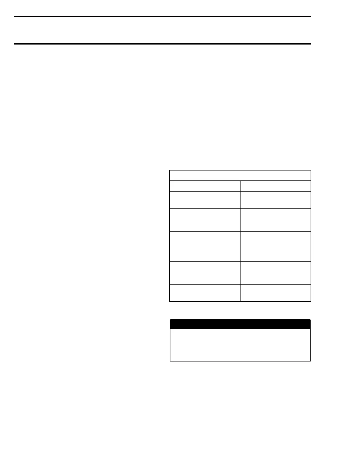
BATTERY
Troubleshooting
SYMPTOM: DISCHARGED OR WEAK BATTERY
CAUSE REMEDY
Battery posts and/or
cable terminal oxidized.
Clean and coat with
dielectric grease.
Loose or bad
connections.
Check wiring and
connector cleanliness,
damaged or short circuit.
Faulty battery (sulfated,
doesn't keep a full
charge, damaged casing,
loose post).
Replace.
Burnt fuse(s) or faulty
rectifier.
First check fuse(s). If
it is in good condition,
check rectifier/regulator.
Faulty battery charging
coil (or stator).
Replace.
Removal
WARNING
Battery BLACK negative cable must always be
disconnected first and connected last. Never
charge or boost battery while installed in wa-
tercraft.
All Models except GTI Series
Proceed as follows:
– Disconnect the BLACK negative cable first.
– Disconnect the RED positive cable last.
– Removetheventlinefromthebattery.
– Remove the holding strap(s).
566 smr2004-Complete Line Up

 Loading...


