Section 16 HULL/BODY
Subsection 01 (ADJUSTMENT AND REPAIR)
FINITION PLATE
Removal and Installation
GTX 4-TEC Series
The removal procedure for RH finition with grid
and LH finition with grid is the same.
Remove the two darts holding the grid to the body.
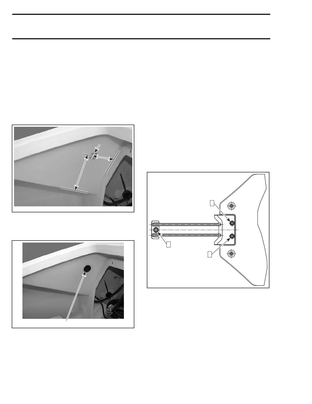
Make a hole into the luggage compartment as
shown in the illustration below to gain access to
the finition plate screw.
155 mm
(6.1 in)
F18L29A
55 mm
(2.2 in)
Ø 25 mm
(1 in)
Remove screw and finition plate.
After installing finition plate, plug (P/N 291 000
279) the finition plate screw hole.
1
F18L2AA
1. Plug (P/N 291 000 279)
GTX 4-TEC Supercharged Limited
Removal procedure for RH finition, deflector with
grid and LH finition, deflector with grid the is
same.
Finition plate is mounted on deflector.
Remove three darts holding deflector and grid.
INLET GRATE
Removal and Installation
Loosen screws and remove inlet grate.
NOTE: An impact screwdriver should be used to
loosen tight screws.
GTI Series and RXP Models
When reinstalling inlet grate, apply Loctite 271 on
threads.
Follow this sequence referring to the illustration:
Hand tighten screws from 1 to 3.
Torquescrews1and2to11N•m(97lbf•in)then
retorque the first screw.
Torquescrew3to26N•m(19lbf•ft).
F16L06A
3
2
1
GTX 4-TEC Series and RXP 4-TEC Models
Follow this sequence referring to the illustration:
Hand tighten screws from 1 to 4.
Torque screw from 1 to 3 to11 N•m(97lbf•in).
Torquescrew4to26N•m(19lbf•ft).
748 smr2004-Complete Line Up

 Loading...


