Section 09 COOLING SYSTEM
Subsection 01 (CIRCUIT, COMPONENTS AND CARE)
1
F18F0CA
2 3
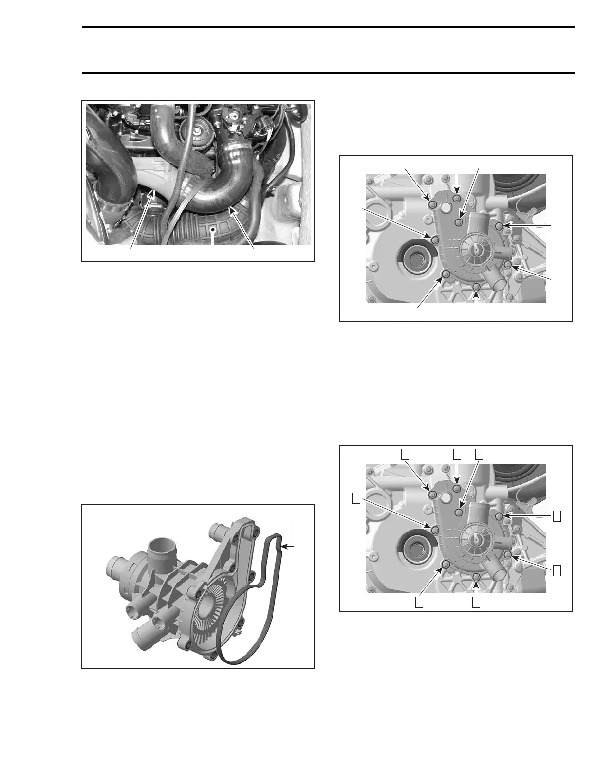
1. Supercharger
2. Inlet hose
3. Outlet hose
All 4-TEC Models
Drain cooling system and engine oil, refer to LU-
BRICATION SYSTEM.
Remove from housing:
– ride plate inlet and outlet hoses
– cylinder head outlet hose no. 1
– oil cooler inlet hose no. 2
– oil cooler outlet hose no. 3
– screws no. 4 and no. 5 retaining coolant pump
housing no. 6
– coolant pump housing no. 6.
Inspection
Check if gasket no. 7 is brittle, hard or damaged
and replace as necessary.
1
F18E11A
1. Weep hole pump housing gasket
Check if thermostat is in good condition. Refer to
THERMOSTAT elsewhere in this section.
Installation
The installation is the opposite of the removal pro-
cedure. Install screws as per the following illus-
tration.
1
2
F18E10A
1
1
1
1
2
1
1. Screws M6 x 25
2. Screws M6 x 105
CAUTION: To prevent leaking, take care that the
gaskets are exactly in groove when you rein-
stall the coolant pump housing.
Apply Loctite 243 on screw threads and torque to
10 N•m(89lbf•in).
Tightening sequence for screws on coolant pump
housing is as per following illustration.
F18E10B
32
4
5
1887
6
THERMOSTAT
The thermostat is a single action type.
smr2004-Complete Line Up 493

 Loading...


