Section 14 STEERING SYSTEM
Subsection 01 (STEERING SYSTEM)
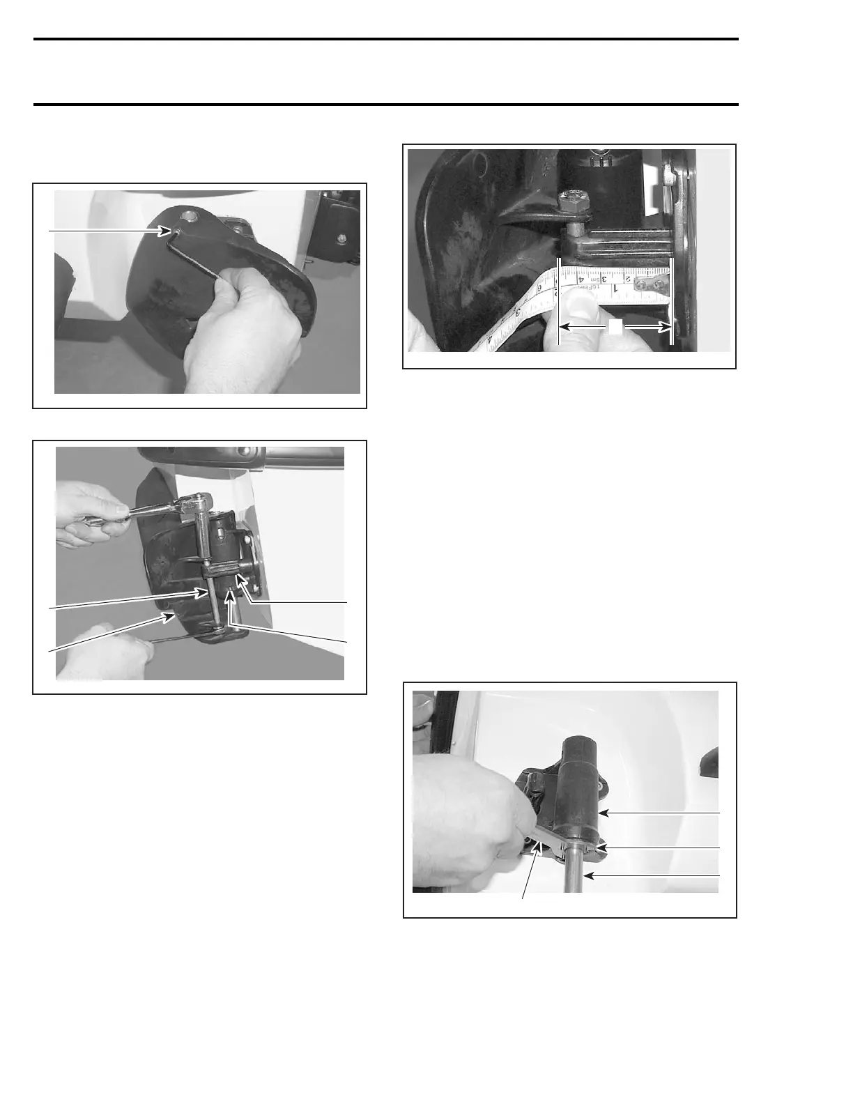
Remove socket screw no. 11 andtierodretaining
screw no. 10.
1
F18K0MA
1. Socket screw
1
2
F18K0LA
4
3
1. Tie rod screw
2. Side vane
3. Cylinder support assembly
4. Tie rod retaining stabilizer
Lift shaft while holding top of side vane.
Pull side vane out.
Adjustment
Put the steering in straight ahead position.
Measure the portion of tie rod stabilizing fitting
no. 21 exceeding from cylinder support.
The exceeding distance of tie rod stabilizing fitting
no. 21 from the cylinder support should be 45 ±
1 mm (1.65 ± .04 in).
A
F18K0ZA
A. 45 ± 1 mm (1.65 ± .04 in)
Assembly
Assembly is the reverse process of disassembly.
Torque tie rod retaining screw no. 10 to 4.5 N•m
(40 lbf•in).
Torque socket screw no. 11 to 2.2 N•m(19lbf•in).
CYLINDER SUPPORT
Disassembly
Removal procedure for RH and LH cylinder sup-
port assembly is same.
Remove side vane as mentioned above.
Unscrew bottom nut using O.P.A.S. cylinder nut
wrench (P/N 529 035 840).
4
F18K0NA
2
1
3
1. Bottom nut
2. Cylinder support
3. Pivot rod
4. O.P.A.S. cylinder nut wrench
Remove cylinder assembly out of cylinder sup-
port.
704 smr2004-Complete Line Up

 Loading...


