Section 13 PROPULSION
Subsection 01 (JET PUMP)
Remove:
– reverse gate
– spring
– pivot arm bolts no. 35 retaining pivot arm and
VTS ring (if so equipped) to nozzle
– nozzle.
XP DI Models
Disconnect steering cable from jet pump nozzle.
Disconnect ball joint of VTS link rod.
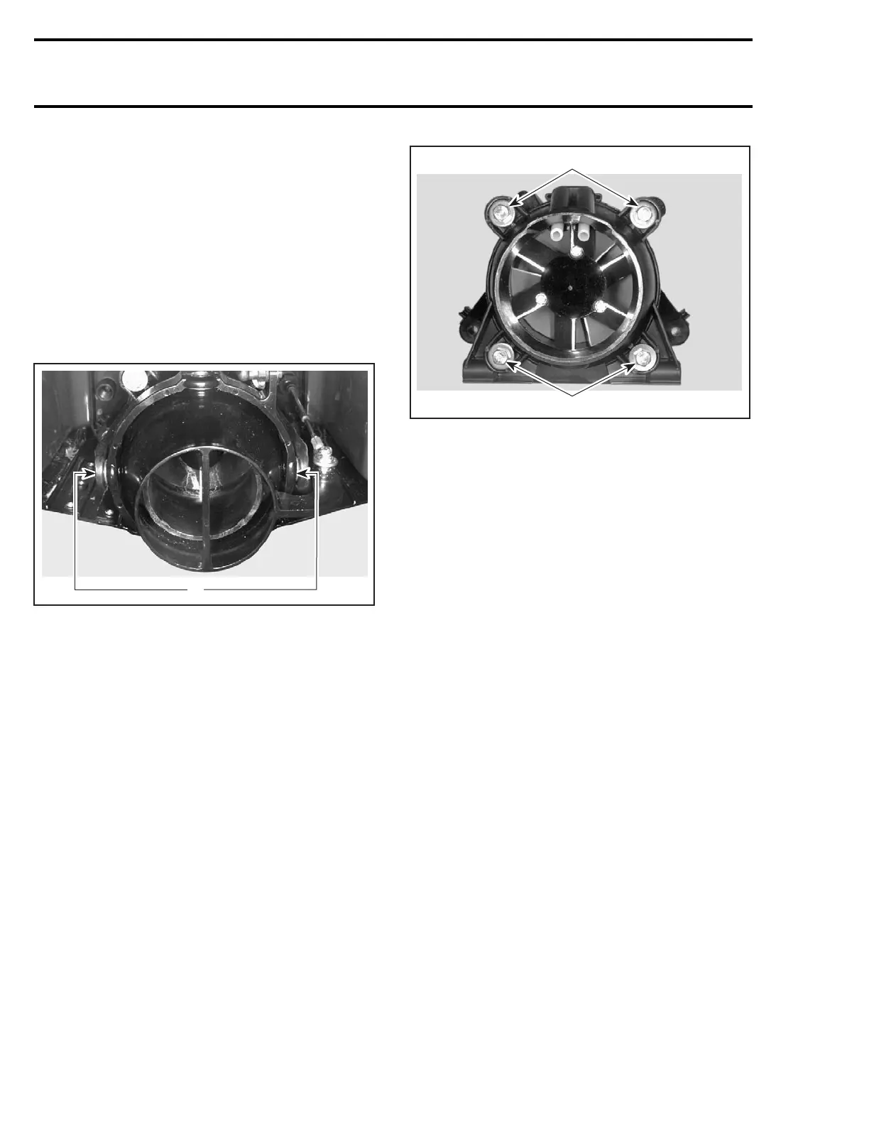
Loosen 2 screws each side of trim ring.
F01J5FA
1
1. Remove screws
Remove nozzle.
Venturi
Remove:
– reverse gate (if so equipped)
– nozzle
– pivot arm (if so equipped).
Remove retaining screws no. 19 and withdraw
venturi no. 18.
It's possible to remove the venturi without remov-
ingthereversegateandthenozzle,seethefol-
lowing instructions.
Disconnect:
– steering cable
– VTS link rod (if so equipped)
– reverse cable (if so equipped).
Remove retaining screws no. 19 and withdraw
venturi no. 18.
F02J0TA
1
1
1. Remove screws
Jet Pump Housing
Remove:
– nozzle
– venturi.
Loosen 4 hexagonal nuts and remove flat washers
and lock washers from jet pump housing.
Removejetpumpwithawigglemovement.
NOTE: After jet pump removal, if drive shaft re-
mains in the PTO flywheel ( except XP DI), simply
pull it out. If drive shaft is seized in the PTO fly-
wheel, refer to DRIVE SYSTEM.
DISASSEMBLY
NOTE: Whenever removing a part, visually check
for damage such as: corrosion, crack, split, break,
porosity, cavitation, deformation, distortion, heat-
ing discoloration, wear pattern, missing plating,
missing or broken needles in needle bearing, wa-
ter damage diagnosed by black-colored spots on
metal parts, etc. Renew any damaged part. As a
quick check, manually feel clearance and end play,
where applicable, to detect excessive wear.
Cover
With pump assembly in horizontal position, re-
move 3 retaining screws no. 17.
Place container under cover no. 16 to catch oil.
620 smr2004-Complete Line Up

 Loading...


