Section 16 HULL/BODY
Subsection 01 (ADJUSTMENT AND REPAIR)
SPONSON REPLACEMENT
Removal and installation procedure for RH and LH
sponson is same.
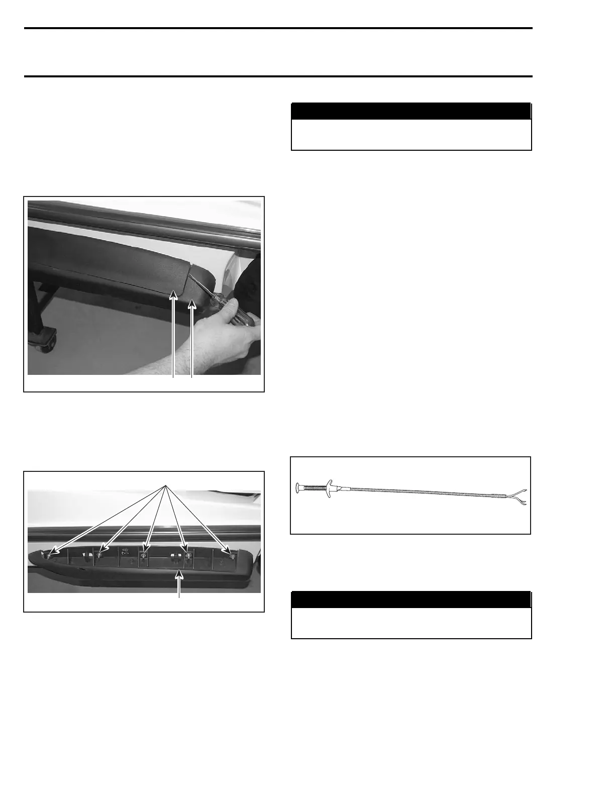
Remove screws no. 11.
Pry out sponson cover from back end with screw-
driver.
2
F18L2BA
1
1. Sponson
2. Sponson cover
Slide sponson cover towards front to about 15 mm
and pull it out from sponson.
Unscrew nut no. 10 and remove sponson no. 8.
1
2
F18L2CA
1. Sponson
2. Nuts
Clean any residues of sealant adhesive on hull.
On installation of sponson, apply silicone sealant
(P/N 293 800 086) around sponson studs.
Apply Loctite 243 on sponson studs and nuts.
Install sponsons no. 8 on hull.
Tighten nuts no. 10 to 7 N•m(62lbf•in).
WARNING
Recommended torques and use of Loctite
must be strictly followed.
Clean hull and sponsons of any sealant adhesive
surplus
Remove seat (access cover for the XP DI models).
Remove seat support (GTI Series).
Remove muffler.
Remove battery.
From inside bilge, remove lock nuts no. 10 using
a 10 mm deep socket with an extension.
Remove sponsons no. 6. Cleananyresiduesof
sealant adhesive on hull.
Install gaskets no. 7 on new sponsons no. 6.
Apply silicone sealant (P/N 293 800 086) around
sponson studs.
Apply Loctite 243 (blue) on sponson studs.
Install sponsons no. 6 on hull.
From inside bilge, first insert flat washers no. 8
over sponson studs. Secure with lock nuts no. 10.
Tightento5N•m(44lbf•in).
NOTE: To ease flat washer and lock washer instal-
lation, use a flexible 4-claw Snap-on pick-up tool.
F01P09A
Reinstall removed parts.
Clean hull and sponsons of any sealant adhesive
surplus.
WARNING
Recommended torques and use of Loctite
must be strictly followed.
ENGINE COMPARTMENT
COVER REMOVAL
XP DI Models
Disconnect throttle and choke cables at carburetor
linkage.
756 smr2004-Complete Line Up

 Loading...


