Section 16 HULL/BODY
Subsection 01 (ADJUSTMENT AND REPAIR)
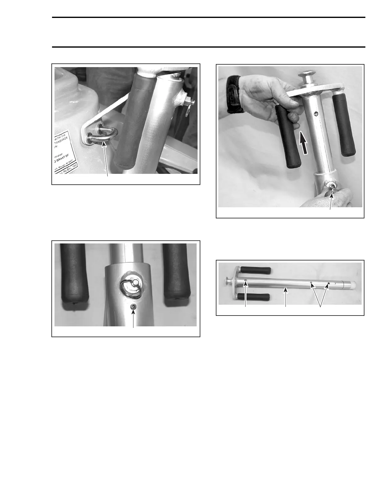
1
F18L38A
1. U-clamp
Remove finition U-clamp no. 21, and screws
no. 25 and pull out wake post no. 20.
Disassembly
Loosen the stopper screw.
1
F18L39A
1. Stopper screw
Pull the safety lock pin to unlock and pull out the
cylinder.
1
F18L3AA
1. Safety lock pin
Assembly
Before assembly verify the physical condition of
cylinder groove and adjustment holes.
2
F18L3BA
12
1. Groove
2. Adjustment holes
Align groove with stopper screw, while inserting
the cylinder into housing.
Tighten the stopper screw.
Installation
Before Installation, make sure:
– inside cylinder slides up and down freely with-
out obstruction from grab handle
– safety lock pin operates properly
– stopper screw stops cylinder at its most up-
wards position.
To install the wake post no. 20, reverse removal
procedure.
smr2004-Complete Line Up 755

 Loading...


