Section 08 ENGINE MANAGEMENT (4-TEC)
Subsection 02 (COMPONENT INSPECTION AND ADJUSTMENT)
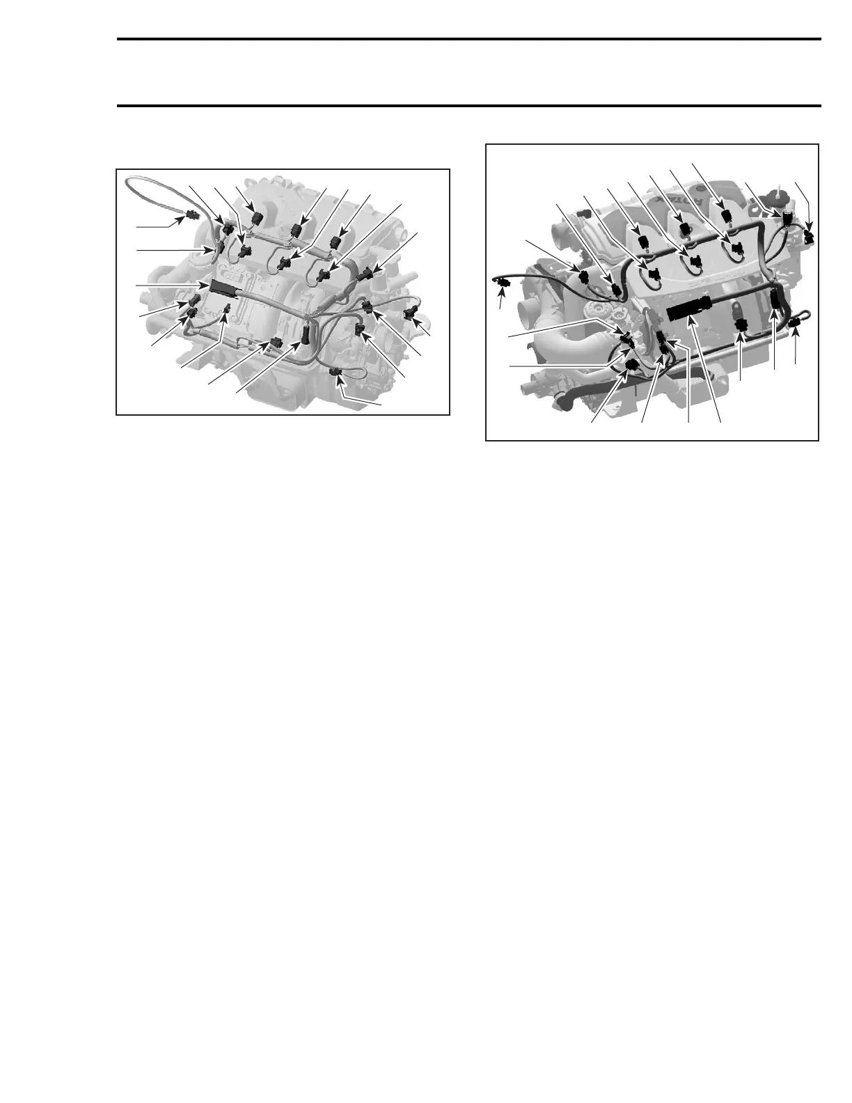
ENGINE WIRING HARNESS
4
R1503motr199A
5
6
78
10
9
11
12
3
2
1
19
20
18
17
14
13
15
16
4-TEC ENGINES
1. ECM connector
2. CTS connector
3. EGTS connector
4. CAPS connector
5. Fuel injector connector (cylinder 1)
6. Ignition coil connector (cylinder 1)
7. Fuel injector connector (cylinder 2)
8. Ignition coil connector (cylinder 2)
9. Fuel injector connector (cylinder 3)
10.Ignition coil connector (cylinder 3)
11. TOPS valve connector
12.OSPS connector
13.TPS connector
14.Idle bypass valve connector
15.MATS connector
16. Engine connector
17.MAPS connector
18.OPS connector
19.KS connector
20. CPS connector
13
4
R1503motr270A
3
2
5
6
7
8
9
10
11
12
14
18
19 20 1
16
15
17
ALL 4-TEC SUPERCHARGED ENGINES
1. ECM connector
2. CTS connector
3. EGTS connector
4. CAPS connector
5. Fuel injector connector (cylinder 1)
6. Ignition coil connector (cylinder 1)
7. Fuel injector connector (cylinder 2)
8. Ignition coil connector (cylinder 2)
9. Fuel injector connector (cylinder 3)
10. Ignition coil connector (cylinder 3)
11.TOPS valve connector
12.OSPS connector
13. TPS connector
14.Idle bypass valve connector
15. MATS connector
16. Engine connector
17.MAPS connector
18.OPS connector
19. KS connector
20.CPS connector
Resistance Test
Check continuity of the circuits according to the
wiring diagram in the WIRING DIAGRAMS section
of this manual.
If wiring harness is good, check the respective
sensor/actuator as described in this section.
Otherwise, repair the connectors, replace the
wiring harness or the ECM/MPEM as diagnosed.
Removal
Remove fuel rail cover.
Disconnect the wiring harness from all sensors/ac-
tuators.
Disconnect the ECM connector from the ECM.
Cut all tie raps which are holding the wiring har-
ness in position.
smr2004-Complete Line Up 419

 Loading...


