Section13PROPULSION
Subsection 01 (JET PUMP)
– pivot arm.
Unplug O.P.A.S. hose from plastic elbow (if appli-
cable).
Remove retaining screws no. 24 and withdraw
venturi no. 23.
It's possible to remove the venturi without remov-
ingthereversegateandthenozzle,seethefol-
lowing instructions.
Disconnect:
– steering cable
1
F18J0KA
1. Steering cable
– O.P.A.S. hose
– reverse cable.
Remove retaining screws no. 24 and withdraw
venturi no. 23.
F02J0TA
1
1
TYPICAL
1. Remove screws
Jet Pump Housing
Remove pump as an assembly or remove the fol-
lowing:
– nozzle
– venturi.
Remove 4 hexagonal nuts/screws from jet pump
housing.
Removejetpumpwithawigglemovement.
CAUTION: When removing pump unit, a shim
could have been installed between hull and
pump housing. Be sure to reinstall it otherwise
engine and jet pump alignment will be altered.
NOTE: If drive shaft is seized in the PTO flywheel,
refer to DRIVE SYSTEM.
DISASSEMBLY
NOTE: Whenever removing a part, visually check
for damage such as: corrosion, crack, split, break,
porosity, cavitation, deformation, distortion, heat-
ing discoloration, wear pattern, missing plating,
missing or broken balls in ball bearing, water
damage diagnosed by black-colored spots on
metal parts, etc. Renew any damaged part. As
a quick check, manually feel clearance and end
play, where applicable, to detect excessive wear.
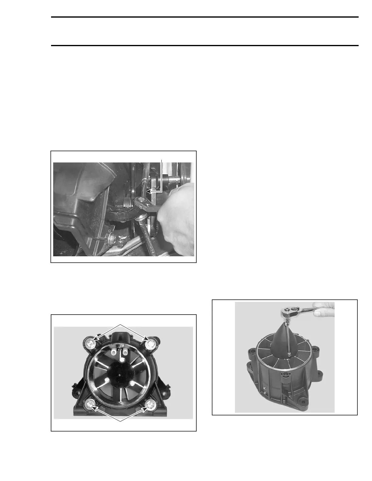
Cover
With pump housing in vertical position, remove 3
retaining screws no. 22.
F18J0LA
Using a fiber hammer, gently tap cover to release
it from jet pump housing. Use flat screwdriver to
remove cap.
smr2004-Complete Line Up 641

 Loading...


