Section12ELECTRICALSYSTEM
Subsection 01 (IGNITION SYSTEM)
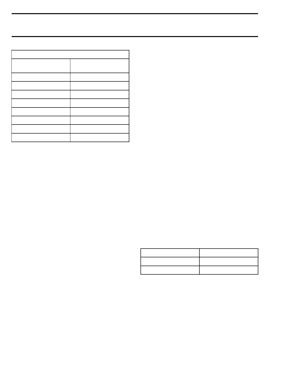
TIMING CORRECTION CHART 787 RFI
MPEM PROGRAMMER
NUMBER
IGNITION TIMING
CORRECTION
1
4.50°
2 3.75°
3 3°
4
2.25°
5
.75°
6 0°
7
-0.75°
8 -2.25°
Ignition timing is set at 12° BTDC at any RPM,
when the Fixed Timing function is active.
PROCEDURE
All Engines
When dealing with ignition problems, the follow-
ing items should be verified in this order:
1) Spark occurrence/spark plug condition.
2) Battery condition.
3) Electrical connections.
4) Engine start/stop switch.
5) Safety lanyard switch.
6) Power supply cut-off relay.
7) Multi-Purpose Electronic Module (MPEM).
8) Magneto output (717 engines).
9) Ignition coil output.
CAUTION: Whenever replacing a component in
ignition system, check ignition timing.
NOTE: To perform verification, a good quality
multimeter such as Fluke 111 (P/N 529 035 868)
should be used.
Engine Start/Stop Switch Verification
Disconnect the YELLOW/RED wire of the
start/stop switch. Using an ohmmeter, con-
nect test probes to YELLOW/RED wire and to
ground.
Measure resistance, it must be an open cir-
cuit (switch is normally open). Depress and hold
switch, the ohmmeter should read close to 0 ohm.
Safety Lanyard Switch Verification
NOTE: The safety lanyard also controls the power
supply cut-off relay. Refer to INSTRUMENTS AC-
CESSORIES for its testing procedure.
If 2 short beeps are not heard when installing the
safety lanyard, refer to DIGITALLY ENCODED SE-
CURITY SYSTEM.
The following continuity tests can also be per-
formed using an ohmmeter:
Disconnect switch wires.
Safety Lanyard Removed
Connect test probes to switch BLACK and
BLACK/YELLOW wires. Measure resistance,
there should be no continuity (open circuit).
Connect one test probe to the WHITE/GRAY wire
and the other test probe to the switch terminal.
Measure resistance, it must be close to 0 ohm.
Connect one test probe to the BLACK wire and
the other test probe to the switch ring. Measure
resistance, it must be close to 0 ohm.
SafetyLanyardonSwitch
Connect test probes to switch BLACK and BLACK/
YELLOW wires. Measure resistance, it must be
close to 0 ohm.
Rev Limiter Verification
To check engine rev limiter, connect an induction
tachometer (P/N 529 014 500), start engine and
check its maximum speed.
MODEL RPM LIMITER SETTING
717
7100 ± 50
787 RFI 7200 ± 50
Multi-Purpose Electronic Module
(MPEM) Verification
It is not possible to accurately check the MPEM
condition without specialized tools. Therefore, re-
place MPEM with a good known unit to conduct
testing.
NOTE: Before replacing the MPEM, make sure all
connectors are properly secured and there is no
water in connectors. Check also the signal and
power contacts in the AMP plug connectors. See
WIRING DIAGRAMS.
552 smr2004-Complete Line Up

 Loading...


