Section10FUELSYSTEM
Subsection 02 (AIR INTAKE (2-STROKE))
GENERAL
During assembly, use the torque values and ser-
vice products as in the exploded views.
Clean threads before applying a threadlocker. Re-
fer to SELF-LOCKING FASTENERS and LOCTITE
APPLICATION at the beginning of this manual for
complete procedure.
WARNING
Torque wrench tightening specifications
must strictly be adhere to.
Locking devices (ex.: locking tabs, elastic
stop nuts, self-locking fasteners, etc.) must
be installed or replaced with new ones where
specified. If the efficiency of a locking device
is impaired, it must be renewed.
REMOVAL
Air Intake Silencer Cover
717 and 787 RFI Engines
Unlock the 6 retaining slides holding air intake si-
lencer cover no. 1.Remove cover and its gasket
no. 2.
F01F2OA
1
2
TYPICAL
1. Air intake silencer cover
2. Unlock
Air Intake Silencer Base
Remove screws no. 3 of retaining plate no. 4.
Pull out retaining plate and air intake silencer base
no. 5.
F00F02A
1
2
1. Retaining plate
2. Remove screws
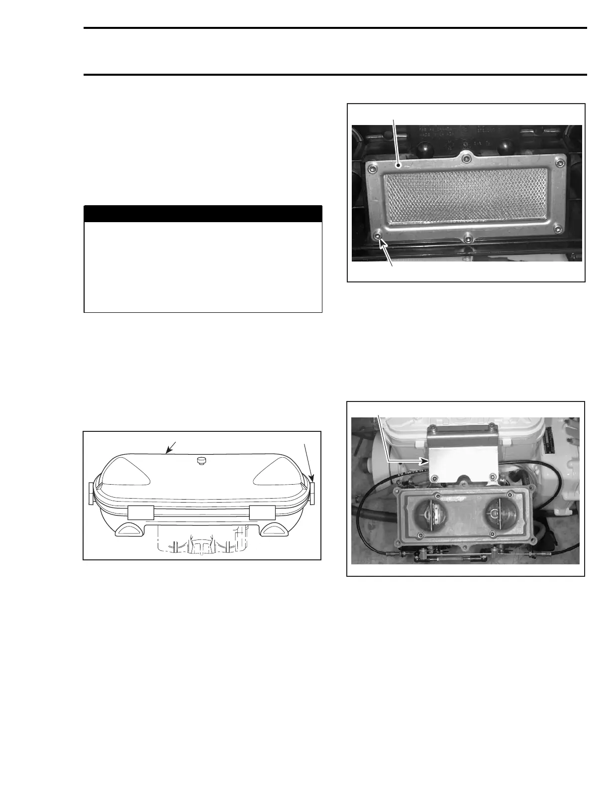
Flame Arrester Base
Remove flame arrester no. 6.
Remove screws no. 7 retaining support no. 8 of
flame arrester base no. 9 to the cylinder head cov-
er (717 engines) or to the exhaust manifold (787
engines).
F00F03A
1
TYPICAL
1. Remove support
Remove screws no. 10 from flame arrester base
then withdraw base.
NOTE: On 717 engines, withdraw both arrester
supports no. 11.
smr2004-Complete Line Up 513

 Loading...


