Section 12 ELECTRICAL SYSTEM
Subsection 02 (CHARGING SYSTEM)
– Connect test probes of the multimeter to the
YELLOW and BLACK/YELLOW wires of the
4-pin magneto harness adapter.
– Start and rev engine to 3500 RPM. The obtained
value should be between 25 and 40 Vac.
– If the battery charging coil is out of specification,
replace it.
Stator
947 DI and 4-TEC Engines
STATIC TEST: CONTINUITY
– Disconnect the magneto wiring harness con-
nector.
– Install the 6-pin magneto harness adapter
(P/N 295 000 136).
NOTE: On 4-TEC engines disconnect the stator
wiring harness connector and probe the three con-
nectors.
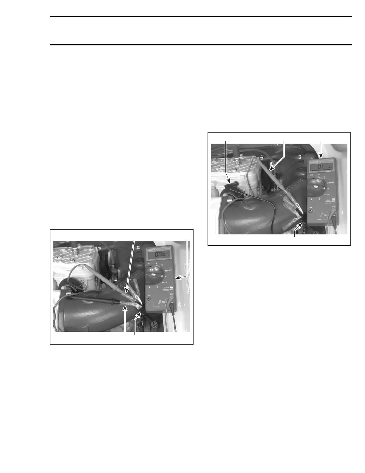
– Check resistance between two of the YELLOW
wires. The resistance should be between 0.1
to 1.0 ohm.
F01H5ZA
13
32
TYPICAL
1. Multimeter
2. Magneto harness adapter
3. YELLOW wires
– Place either meter lead into the remaining YEL-
LOW wire and note the resistance (same as
step no. 3). If the readings are out of speci-
fication, the stator will need to be replaced.
STATIC TEST: INSULATION
– Disconnect the magneto wiring harness con-
nector.
– Install the 6-pin magneto harness adapter
(P/N 295 000 136) to the magneto wiring har-
ness. Leave wiring harness side disconnected.
– Insert multimeter positive (+) probe to one of
the YELLOW wire of the 6-pin magneto harness
adapter.
– Ground the multimeter negative (-) probe to the
engine or the stator iron core and note the read-
ing.
F01H60A
1
3
2
4
TYPICAL
1. Multimeter
2. Magneto harness adapter
3. Positive (+) probe to YELLOW wire
4. Negative (-) probe to ground
– Repeat test with the other two YELLOW wires
of the 6-pin magneto harness adapter.
NOTE: There should be no continuity (infinity) be-
tween the stator insulated coils and ground. If
there is a reading, the stator coils and/or the wiring
from the coils is grounded and needs to be re-
placed or repaired.
DYNAMIC TEST — AC Voltage
– Disconnect the voltage regulator/rectifier con-
nectors.
– Disconnect the magneto wiring harness con-
nector.
– Install the 6-pin magneto harness adapter
(P/N 295 000 136) between connectors.
NOTE: On 4-TEC engines disconnect the stator
wiring harness connector and probe the three con-
nectors.
– Connect test probes of the multimeter to two
of the YELLOW wires of the 6-pin magneto har-
ness adapter.
smr2004-Complete Line Up 565

 Loading...


