Section12ELECTRICALSYSTEM
Subsection 02 (CHARGING SYSTEM)
Connect the positive probe of a multimeter to the
RED wire and the negative probe to the BLACK
wire.
Set multimeter to Vdc scale.
Start and rev engine to 3500 RPM. The obtained
value should be between 12 and 25 Vdc.
NOTE: If the rectifier/regulator is within the spec-
ification, either the MPEM or wiring harness be-
tween the rectifier and battery is defective. If the
rectifier/regulator is out of specification and the
battery charging coil (or stator) test good, the rec-
tifier/regulator is defective.
Battery Charging Coil
717 Engines
STATIC TEST: CONTINUITY
– Disconnect the magneto wiring harness con-
nector.
– Install the 4-pin magneto harness adapter
(P/N 295 000 131) to the magneto wiring har-
ness. Leave wiring harness side disconnected.
– Check resistance between the YELLOW and
BLACK/YELLOW wires of the magneto harness
adapter. Refer to the following table.
PART NAME WIRE COLOR RESISTANCE
Battery
charging coil
YELLOW with
BLACK/YELLOW
0.05 - 0.6
NOTE: A short circuit will read 0 ohm (or close to)
on ohmmeter.
F02H0KA
1
23
1. Multimeter
2. Magneto harness adapter
3. YELLOW and BLACK/YELLOW wires
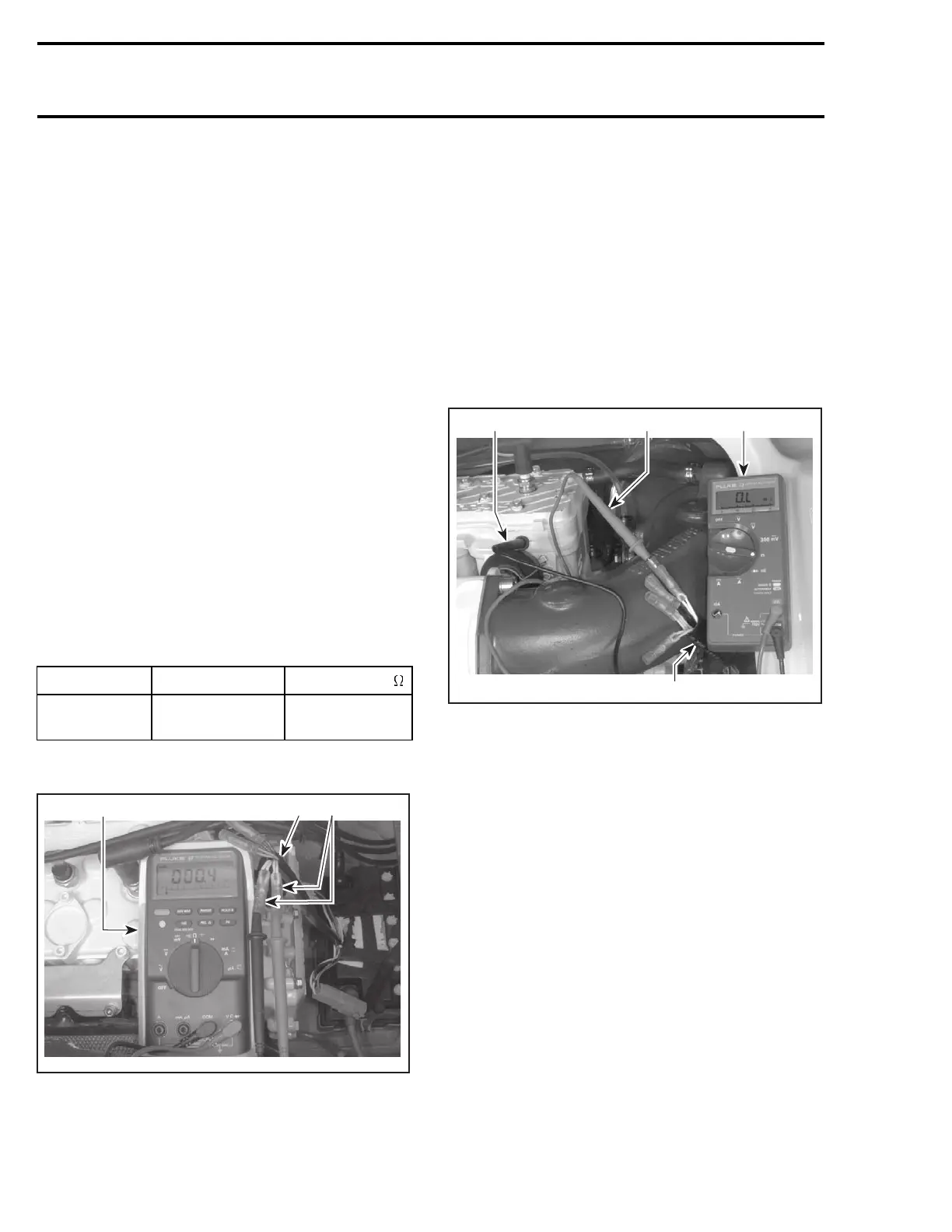
STATIC TEST: INSULATION
– Disconnect the magneto wiring harness con-
nector.
– Install the 4-pin magneto harness adapter
(P/N 295 000 131) to the magneto wiring har-
ness. Leave wiring harness side disconnected.
– Insert multimeter positive (+) probe to the
YELLOW wire of the 4-pin magneto harness
adapter.
– Ground the multimeter negative (-) probe to the
engine or the stator iron core and note the read-
ing.
F01H60A
1
3
2
4
TYPICAL
1. Multimeter
2. Magneto harness adapter
3. Positive (+) probe to YELLOW wire
4. Negative (-) probe to ground
– Repeat test with the other two YELLOW/
BLACK wires of the 4-pin magneto harness
adapter.
NOTE: There should be no continuity (infinity) be-
tween the stator insulated coils and ground. If
there is a reading, the stator coils and/or the wiring
from the coils is grounded and needs to be re-
placed or repaired.
DYNAMIC TEST — AC Voltage
– Disconnect the voltage regulator/rectifier con-
nector.
– Disconnect the magneto wiring harness con-
nector.
– Install the 4-pin magneto harness adapter
(P/N 295 000 131) between connectors.
564 smr2004-Complete Line Up

 Loading...


