Section 12 ELECTRICAL SYSTEM
Subsection 04 (INSTRUMENTS AND ACCESSORIES)
VTS Position Indicator
XP DI Models
Disconnect the AMP connector #1 from the
MPEM.
Using an appropriate terminal remover, remove
the BROWN/WHITE and BROWN/BLACK wires
from the AMP connector.
Connect potentiometer test probes to the
BROWN/WHITE and BROWN/BLACK wires.
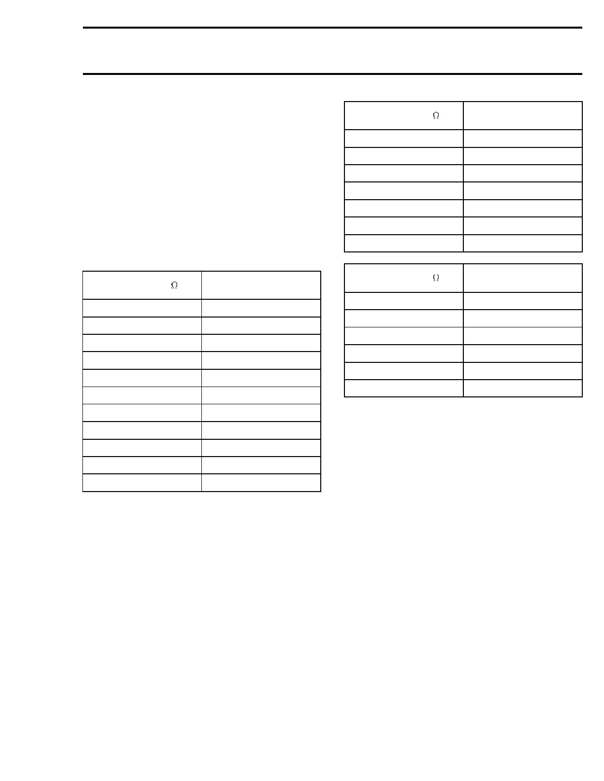
Adjust potentiometer to the resistance values as
per following chart to test the accuracy of the In-
formation Center.
RESISTANCE ( )
VTS DISPLAYED LCD
SEGMENT
167.3 ± 2.2 11/11 (UP)
153.0 ± 2.2 10/11
138.7 ± 2.2 9/11
124.4 ± 2.2 8/11
110.1 ± 2.2 7/11
95.8 ± 2.2 6/11
81.5 ± 2.2 5/11
67.2 ± 2.2 4/11
52.9 ± 2.2 3/11
38.6 ± 2.2 2/11
24.3 ± 2.2
1/11 (DOWN)
Water Temperature (L temp)
GTI LE RFI Model
The water temperature sensor is integrated with
the speed sensor located on the ride plate. As a
result, that sensor has 3 wires instead of 2.
Disconnect the AMP connector #1 from the
MPEM.
Using an appropriate terminal remover, remove
the BLACK/ORANGE and TAN/ORANGE wires
from the AMP connector.
Connect potentiometer test probes to the BLACK/
ORANGE and TAN/ORANGE wires.
Adjust potentiometer to the resistance values as
per following chart to test the accuracy of the In-
formation Center.
RESISTANCE ( )
DISPLAY
TEMPERATURE (°C)
25407.3 5±2
19911.1 10 ± 2
15718.0 15 ± 2
12495.0 20 ± 2
10000.0 25 ± 2
8054.9 30 ± 2
6528.3 35 ± 2
RESISTANCE ( )
DISPLAY
TEMPERATURE (°F)
22799.0
45 ± 4
17262.0
55 ± 4
13470.0 65 ± 4
10496.3
75 ± 4
8264.4 85 ± 4
6528.3 95 ± 4
Exterior Temperature
GTI LE RFI Model
Disconnect the 2-circuit connector housing of the
Information Center which contains a TAN/WHITE
and BLACK/WHITE wires.
Connect potentiometer test probes to the TAN/
WHITE and BLACK/WHITE wires.
Adjust potentiometer to the resistance values as
per following chart to test the accuracy of the In-
formation Center.
smr2004-Complete Line Up 601

 Loading...


