Section12ELECTRICALSYSTEM
Subsection 04 (INSTRUMENTS AND ACCESSORIES)
RESISTANCE ( ) TEMPERATURE (°C)
4712 5±2
3792 10 ± 2
3069 15 ± 2
2500 20 ± 2
2057 25 ± 2
1707 30 ± 2
1412 35 ± 2
RESISTANCE ( ) TEMPERATURE (°F)
4316
45 ± 4
3337
55 ± 4
2712 65 ± 4
2138
75 ± 4
1771
85 ± 4
1412 95 ± 4
Information Center
4-TEC Models
When there is no display at the information center,
perform the following:
– B.U.D.S. can be used to check its operation.
Look in the Monitoring tab.
– Check fuses.
– Check supply wire (1-23) and ground wire (1-8)
from MPEM.
– Check communication link wires (WHITE/RED
and WHITE/BLACK):
• To quickly check if the communication link is
working, temporarily disconnect a sensor on
theenginetocreateafaultcode. Startthe
engine. The information center should dis-
play a fault code when in onboard diagnostic
mode.
• Check if wires are swapped, unconnected or
short circuit.
• One faulty wire will cause a longer delay to
perform the self-test when safety lanyard is
installed.
– If everything tests good, try a new information
center.
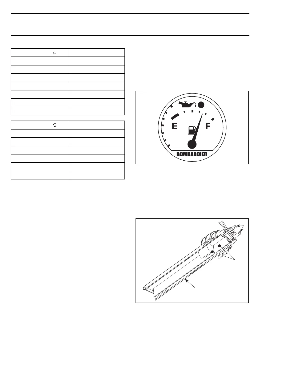
Fuel/Oil Gauge/Low Oil Warning Light
GTI, GTI LE and GTI RFI Models
The fuel gauge has a pointer which indicates fuel
level in the tank.
The low oil warning light is part of the gauge. It
will light when injection oil level is low.
F07H0OA
TYPICAL
Fuel Baffle Pick-Up Sender
GTI and GTI LE Models
The baffle pick-up has an integrated fuel sender.
To verify fuel sender, a resistance test should be
performed with a multimeter allowing the float to
move up through a sequence.
F01F20A
1
2
3
1. Pick-up tube
2. Fuel sender
3. Baffle pick-up
The resistance measured between PINK/BLACK
and PINK wires must be in accordance with fuel
level (measured from under the flange) as speci-
fied in the following charts.
602 smr2004-Complete Line Up

 Loading...


