Section 12 ELECTRICAL SYSTEM
Subsection 04 (INSTRUMENTS AND ACCESSORIES)
FUEL LEVEL AND RESISTANCE
FUEL LEVEL (mm) RESISTANCE ( )
From 248.9 ± 5 and more 0+2.2
From 234.4 to 248.8 ± 5 17.8 ± 2.2
From 200.9 to 234.3 ± 5 27.8 ± 2.2
From 167.4 to 200.8 ± 5 37.8 ± 2.2
From 134.0 to 167.3 ± 5 47.8 ± 2.2
From 100.5 to 133.9 ± 5 57.8 ± 2.2
From 67.0 to 100.4 ± 5 67.8 ± 2.2
From 40.1 to 66.9 ± 5 77.8 ± 2.2
From 0 to 40.0 ± 5 89.8 ± 2.2
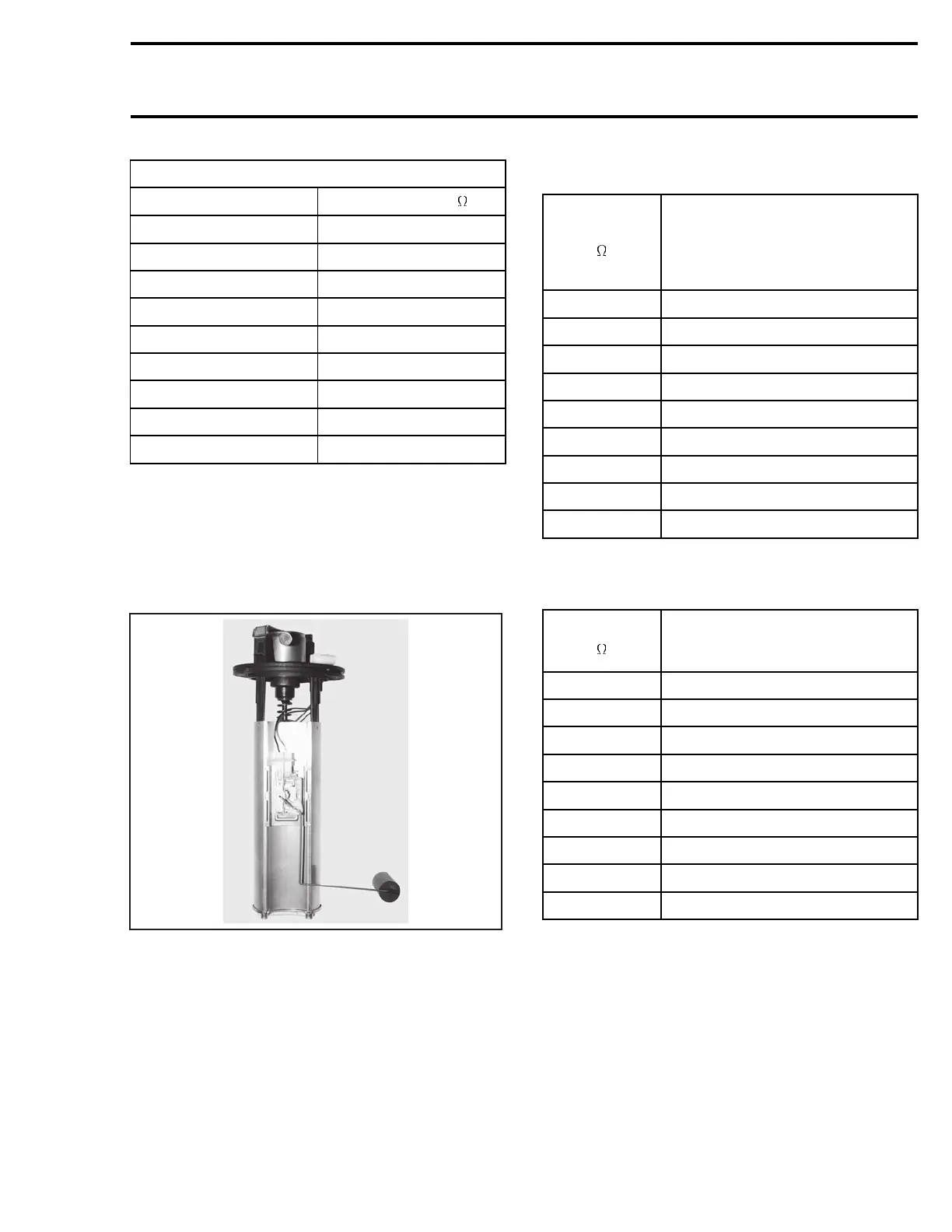
RFI, DI and 4-TEC Models
The fuel pick-up system is part of the fuel pump
module mounted inside the fuel reservoir.
The fuel level gauge sender is also mounted on
this module.
F07F09A
TYPICAL — FUEL LEVEL GAUGE SENDER MOUNTED
ON FUEL PUMP MODULE
Refer to ENGINE MANAGEMENT for fuel pump
testing. For fuel level sensor, follow procedures
below.
The resistance measured between PINK/BLACK
and PINK wires must be in accordance with fuel
level (measured from under the flange) as speci-
fied in the following charts.
RFI Models
RESISTANCE
(
)
FLOAT HEIGHT
(bottom of float with
bottom the sensor sends
the signal to the low-oil level
of pump module) (mm)
4.8 + 2.2 228 ± 5.0
17.8 ± 2.2 186 ± 5.0
27.8 ± 2.2 164 ± 5.0
37.8 ± 2.2 139 ± 5.0
47.8 ± 2.2 114 ± 5.0
57.8 ± 2.4 86 ± 5.0
67.8 ± 2.8 57 ± 5.0
77.8 ± 3.6 36 ± 5.0
89.8 ± 3.6 16 ± 5.0
XP DI and 4-TEC Models
RESISTANCE
(
)
FLOAT HEIGHT
(bottom of float with
bottom of pump module) (mm)
4.8 ± 2.2 247 ± 5.0
17.8 ± 2.2 207 ± 5.0
27.8 ± 2.2 183 ± 5.0
37.8 ± 2.2 158 ± 5.0
47.8 ± 2.2 133 ± 5.0
57.8 ± 2.4 105 ± 5.0
67.8 ± 2.8 76 ± 5.0
77.8 ± 3.6 55 ± 5.0
89.8 ± 3.6 35.3 ± 5.0
Oil Sensor
The sensor sends the signal to the low-oil level
light in the fuel gauge or the LED in the Information
Center.
smr2004-Complete Line Up 603

 Loading...


