Section12ELECTRICALSYSTEM
Subsection 04 (INSTRUMENTS AND ACCESSORIES)
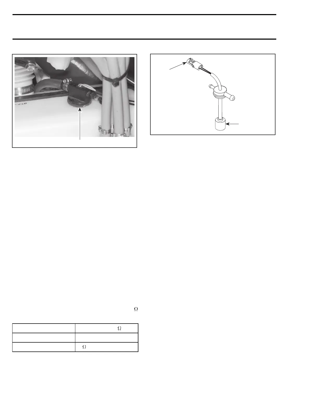
F00H0LA
1
1. Oil sensor
The bottom of the sensor has a small reservoir
with two small holes underneath to let the oil en-
ter inside and one at the top to let the air enter
allowing the oil to flow out.
When there is enough oil inside the oil tank (and
therefore in the sensor reservoir), the sensor de-
tectstheliquidandthelightDOESNOTturnon.
When the oil level goes at critical LOW level inside
the oil tank (and therefore in sensor reservoir), the
sensor detects the absence of liquid and the light
TURNS ON.
To check the oil sensor, unplug its connector and
pull sensor out of oil tank.
Using a multimeter, check the continuity between
the BLUE and BLUE/BLACK terminals.
When sensor is out of oil tank and its reservoir is
empty, resistance must be infinite (open circuit).
NOTE: Wait about 15 - 20 seconds before taking
any reading to give the oil enough time to flow out
or inside sensor reservoir.
Soak sensor in oil so that its reservoir fills up.
Maximumresistanceshouldbeapproximately2
(closed circuit).
TEST CONDITION READING ( )
Sensor OUT of oil
∞ (open circuit)
Sensor soaked IN oil
2 max. (closed circuit)
F03H0BA
1
2
1. Measure resistance here
2. Sensor reservoir
To Reinstall Sensor:
– Remove rubber seal from sensor.
– Install seal in oil tank hole.
– Push sensor in seal.
– Plug connector.
NOTE: This sensor turns the LED to ON if the
connector has been forgotten unconnected even
when there is enough oil in tank.
VTS Switch
XP DI and RXP Models
Alwaysconfirmfirstthatthefuseisingoodcon-
dition.
Disconnect BLACK wire, BLUE/WHITE wire and
GREEN/WHITE wire of VTS switch.
Using a multimeter, connect test probes to switch
BLACK and BLUE/WHITE wires; then, connect
test probes to switch BLACK and GREEN/WHITE
wires.
Measure resistance; in both test it should be high
when button is released and must be close to zero
when activated.
VTS Motor
XP DI and RXP Models
Alwaysconfirmfirstthatthefuseisingoodcon-
dition.
The fuse is located on the MPEM module.
Motor condition can be checked with a multi-
meter. Install test probes on both RED/PUR-
PLE/WHITE and ground wires of the 2-circuit con-
nector housing. Measure resistance, it should be
closeto1.5ohm.
604 smr2004-Complete Line Up

 Loading...


