Section 12 ELECTRICAL SYSTEM
Subsection 04 (INSTRUMENTS AND ACCESSORIES)
If motor seems to jam and it has not reached the
end of its stroke, the following test could be per-
formed.
First remove motor, refer to VARIABLE TRIM SYS-
TEM. Then manually rotate worm to verify VTS
system actuating mechanism for free operation.
Connect motor through a 15 A fuse directly to the
battery.
Connect wires one way then reverse polarities to
verify motor rotation in both ways.
If VTS actuating mechanism is correct and the mo-
tor turns freely in both ways, VTS module could be
defective.
If VTS motor does not stop at the end of its stroke
while installed, the motor could be defective.
VTS Control Module
XP DI and RXP Models
It receives its current from the battery. It is pro-
tected by its own fuse located on the MPEM mod-
ule.
Resistance Test
Disconnect BROWN/BLACK wire and BROWN/
WHITE wire of VTS control module.
Connect test probes of a multimeter to BROWN/
BLACK wire and BROWN/WHITE wire of VTS con-
trol module.
PushonVTSswitchdownpositionuntilmotor
stops.
Readtheresistanceontheohmmeter,itshould
indicate a resistance of 24 ohms ± 1%.
Push on VTS switch up position until motor stops.
Readtheresistanceontheohmmeter,itshould
indicate a resistance of 167 ohms ± 1%.
RESISTANCE ( ) NOZZLE POSITION
167 ± 1%
24 ± 1%
UP
DOWN
NOTE: If the VTS control module passes this re-
sistance test, it doesn't mean it is in perfect con-
dition.
Water Temperature Sensor
GTI LE RFI and 4-TEC Models
The water temperature sensor is integrated with
the speed. As a result, that sensor has 3 wires
instead of 2.
On 4-TEC models, B.U.D.S. can be used to check
its operation. Look in the Monitoring tab.
To check if the water temperature sensor is oper-
ational, select the water temperature mode in the
Information Center.
With a garden hose, spray the speed sensor with
water. The temperature reading on the Informa-
tion Center should adjust to the water tempera-
ture.
If not, replace the speed sensor.
Exterior Temperature Sensor
GTI LE RFI and 4-TEC Models
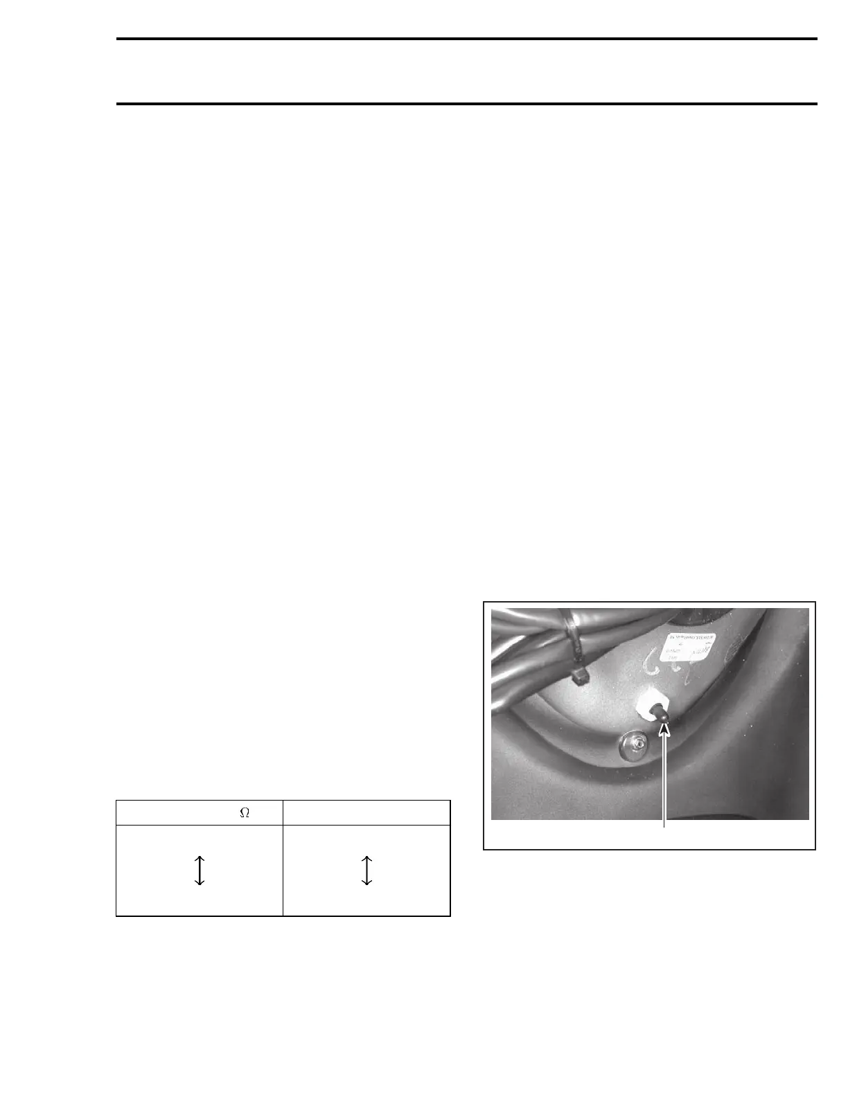
The temperature sensor is located in the storage
cover.
On 4–TEC models, B.U.D.S. can be used to check
the operation. Look in the Monitoring tab.
Remove the back panel of the storage cover to
access the temperature sensor.
F07H01A
1
1. Temperature sensor
To check if the temperature sensor is operational,
select the exterior temperature mode in the Infor-
mation Center.
Use a heat gun to warm up the sensor. The tem-
perature should raise rapidly on the gauge.
smr2004-Complete Line Up 605

 Loading...


