Section 05 ENGINE (4-TEC)
Subsection 08 (ENGINE BLOCK)
1
R1503motr08A
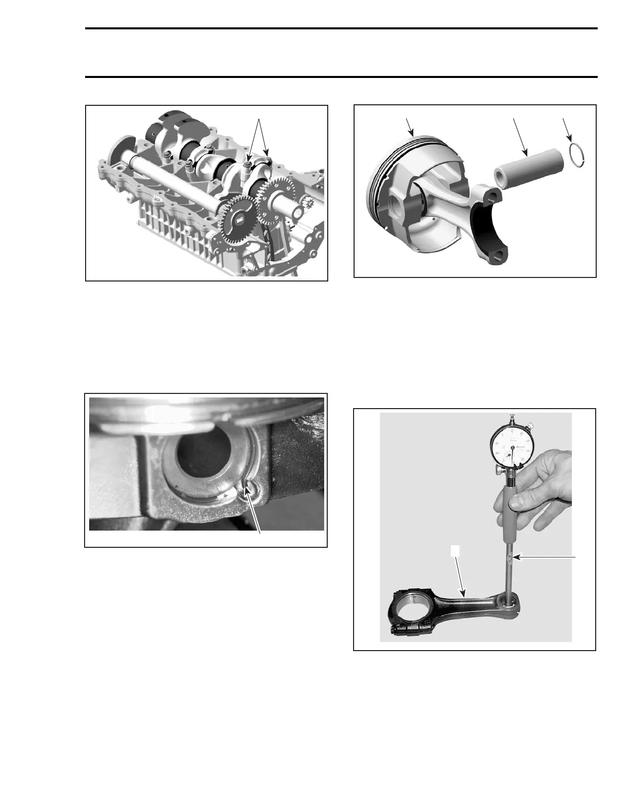
1. Connecting rod screws
NOTE: Before removing the connecting rod bear-
ing caps, mark them to remember the right posi-
tion when reassembling.
Pull piston with connecting rod out of the cylin-
ders.
Remove one piston circlip no. 8 and discard it.
1
R610motr134A
1. Piston circlip
NOTE: The removal of both piston circlips is not
necessary to remove piston pin.
Push piston pin no. 9 outofpiston.
1
R1503motr27A
32
1. Piston
2. Piston pin
3. Circlip
Detach piston no. 10 from connecting rod.
Inspection
Connecting Rod/Piston Pin Clearance
Measure piston pin. Compare to inside diameter
of connecting rod no. 5.
1
R610motr73A
2
1. Bore gauge
2. Connecting rod
smr2004-Complete Line Up 289

 Loading...


