Section 09 COOLING SYSTEM
Subsection 01 (CIRCUIT, COMPONENTS AND CARE)
The water flow is controlled by a reducer located
between the jet pump support and the jet pump
on the inlet side. The reducer is color coded ac-
cording to watercraft model. Refer to JET PUMP.
4-TEC Supercharged Intercooled Engines
Water is directed first through the intercooler.
All 4-TEC Engines
Water is directed to the exhaust manifold fitting
located at front of manifold.
2
3
F18E1FA
1
TYPICAL
1. Exhaust manifold
2. Water inlet
3. Water outlet
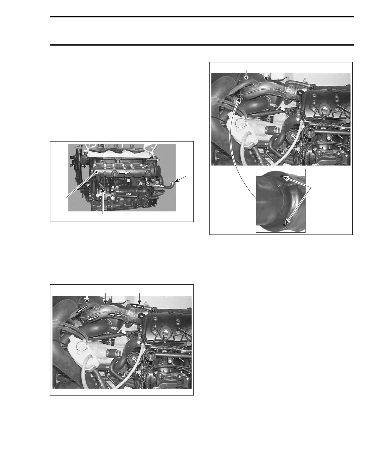
Water enters the manifold end and is directed to
water jackets of exhaust manifold.
Water exits exhaust manifold through 2 hoses at
rear manifold.
1
F18E1EA
23
TYPICAL
1. Water coming from exhaust manifold
2. Exhaust pipe
3. Bleed hose
Water enters exhaust pipe and flows in the water
jacket of pipe.
2
F18E1GA
13
TYPICAL
1. Exhaust pipe
2. Outlet holes of exhaust pipe
3. Muffler
Bleeding of the exhaust system is accomplished
by the bleed hose located at the upper most point
of the circuit of the exhaust pipe.
Water exits exhaust pipe through holes at the end
of the water packet and mixes with exhaust gas
in the muffler.
Water is expulsed from mufflers then through the
exhaust outlet in transom area.
Clamp
To cut or secure non-reusable Oetiker clamps of
cooling system hoses, use pliers (P/N 295 000
070).
smr2004-Complete Line Up 489

 Loading...


