58 TimeProvider 2300/2700 User’s Guide 098-00564-000 Revision A3 – July, 2013
Chapter 2 Installing
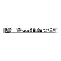
Applying Power to the TimeProvider 2300/2700
Normal Power Up Indications
As the TimeProvider 2300/2700 powers up and begins normal operation, the LEDs
all turn on. After the self-test is complete and the firmware is operational, the LED
states may change to indicate the appropriate state or status.
Table 2-8 provides a description of the TP 2300/2700 LEDs.
Table 2-8. LED Descriptions
Label LED Description
POWER Power
Module Power Indicator
Green - Power available
Off - Power not available
PWR A -48V A-Bus
A-Bus Battery Indicator
Off - A-No Power
Green - A-Bus power OK
PWR B -48V B-Bus
B-Bus Battery Indicator
Off - B-No Power
Green - A-Bus power OK
CLOCK Clock Status Green - Time or Frequency clock in Normal or
Bridging state
Flashing Green - Time or Frequency clock in
Fast Lock or Recovery state
Amber - Time or Frequency clock in Freerun or
Holdover state
Flashing Amber - Clock in Warmup state
ALARM Alarm
System alarm/fault indicator
Off -Operating normally
Amber - Minor Alarm(s)
Red - Major/Critical Alarm(s)
GNSS GNSS Status
GPS / GLONASS engine status
indicator
Green - GNSS enabled and GNSS
engine/interface is operating and tracking
normally
Amber - GNSS enabled and GNSS engine or
antenna interface has operational issues, not
tracking normally
Red - Short circuit or open circuit
Off - GNSS disabled or not installed
MGMT Ethernet Management Port
LEDs on the Ethernet connector
Left Flashing Green - Activity for 10/100/1000M
Left Green - Link Established for 10/100/1000M
Left Off - Link has not been established
Right Amber - Link established for 100M
Right Green - Link established for 1000M
Right Off -No link for 100/1000M
ETH1 -S1 Ethernet Port 1 - SFP (s1)
LEDs on the Ethernet connector
Green - Activity on link for 1000M
Off - No Activity
 Loading...