Multi Pro 5800 Hydraulic SystemPage 5 − 37
Traction Circuit − Traction (Piston) Pump and Relief
Pressure Test
This test should be performed to measure the piston
(traction) pump output (flow) and to make sure the for-
ward and reverse traction circuit relief pressures are
correct.
IMPORTANT: If component failure is suspect, see
Traction Circuit Component Failure in the General
Information section of this chapter for information
regarding the importance of removing contamina-
tion from the traction circuit before operating the
system.
NOTE: Traction circuit flow for the Multi Pro 5800 is
approximately 30 GPM (113.5 LPM). Use 40 GPM Hy-
draulic Tester #AT40002 (pressure and flow) for this test
(see Special Tools in this chapter).
1. Park machine on a level surface, stop engine, en-
gage parking brake and remove key from the ignition
switch. After turning engine off, operate all hydraulic
controls to relieve hydraulic system pressure.
CAUTION
Prevent personal injury and/or damage to equip-
ment. Read all WARNINGS, CAUTIONS and Pre-
cautions for Hydraulic Testing at the beginning
of this section.
2. Make sure that traction pedal is adjusted to the neu-
tral position (see Adjust Traction Pedal for Neutral in this
chapter). Also, ensure that traction pump is at full stroke
when pedal is pushed to fully forward position.
3. Raise and support machine so rear wheels are off
the ground (see Jacking Instructions in Chapter 1 −
Safety).
4. Remove the rear undercarriage shroud (see Under-
carriage Shrouds in Chapter 9 − Chassis in this manual).
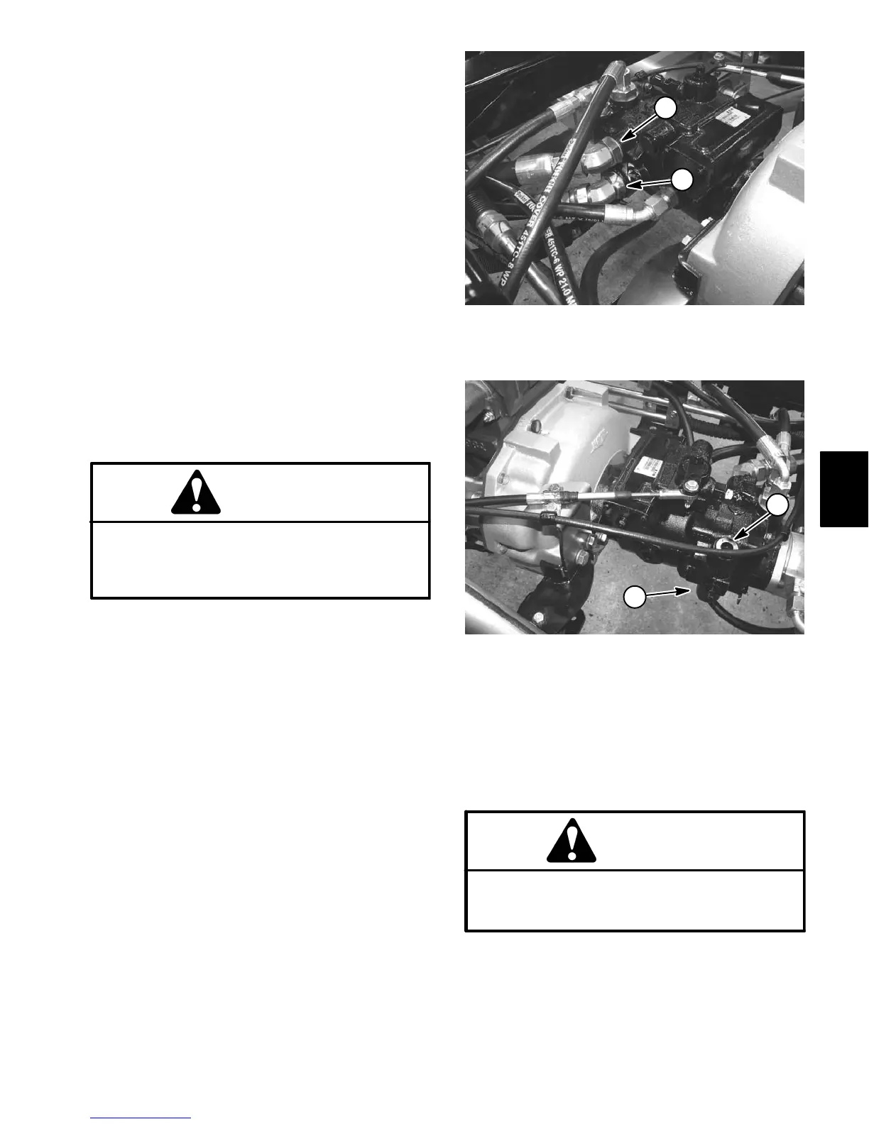
5. Clean hydraulic hoses and fittings on right side of
pump (Fig. 30).
6. Disconnect the upper hose to test forward direction
relief pressure and pump flow, or disconnect the lower
hose to test reverse direction relief pressure.
IMPORTANT: Make sure that the oil flow direction
indicator on the flow meter is showing that the oil
will flow from the pump, through the tester and into
the hydraulic hose.
1. Forward direction
(upper fitting)
2. Reverse direction
(lower fitting)
Figure 30
2
1
1. Forward relief valve
(upper)
2. Reverse relief valve
(lower)
Figure 31
2
1
7. Install 40 GPM Hydraulic Tester #AT40002 (pres-
sure and flow) in series between piston pump fitting and
disconnected hose. Use hydraulic hose kit (see Special
Tools in this chapter) to connect tester to machine. Make
sure that flow control valve on tester is fully open.
CAUTION
Use extreme caution when performing traction
pump flow tests. The traction unit wheels will be
rotating during the test.
Hydraulic
System

 Loading...


