Multi Pro 5800Hydraulic System Page 5 − 72
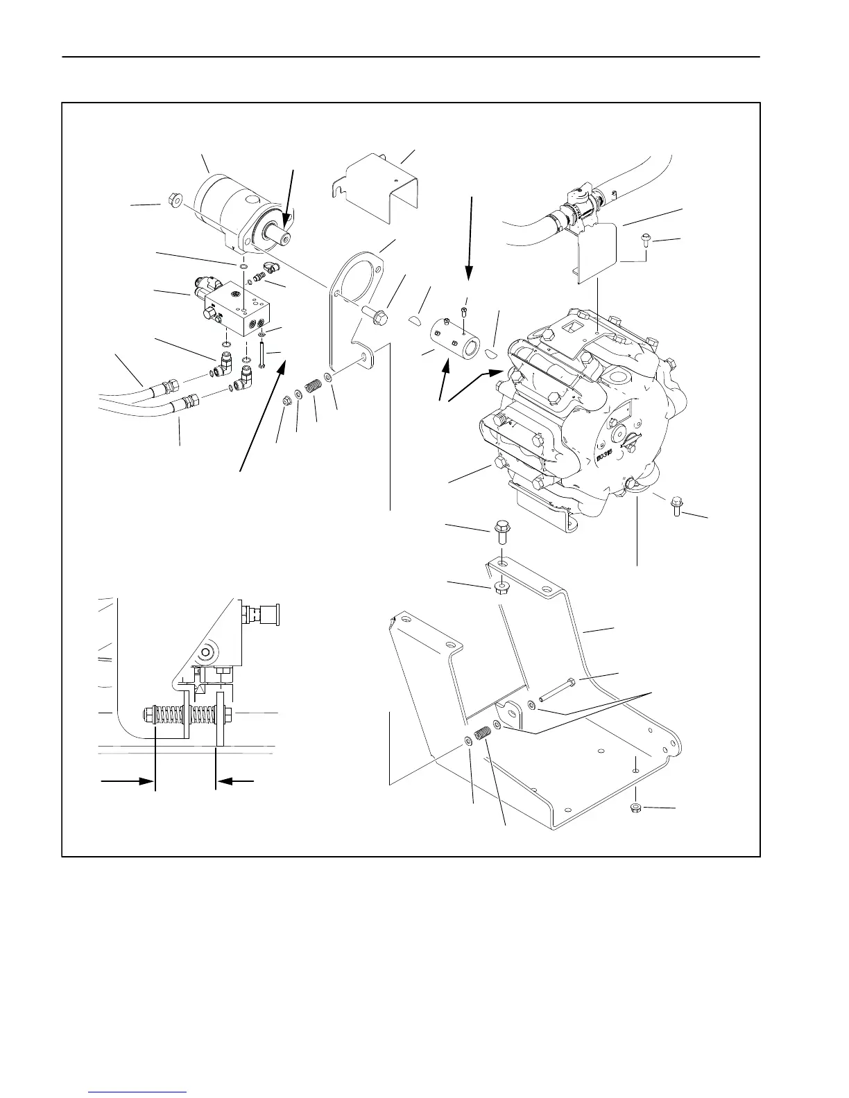
Spray Pump Drive Motor and Control Manifold Assembly
Figure 53
1. Hydraulic motor
2. Flange nut (2)
3. Guard
4. Motor mount plate
5. Flange head screw (2)
6. Woodruff key
7. Set screw (4)
8. Coupler
9. Woodruff key
10. Valve bracket
11. Flange head screw (2)
12. Flange head screw (4)
13. Pump bracket
14. Cap screw
15. Flat washer (5)
16. Flange nut (4)
17. Compression spring (2)
18. Lock nut
19. Flange nut (4)
20. Flange head screw (4)
21. Spray pump
22. Flat washer (4)
23. Cap screw (4)
24. Hydraulic hose (to oil cooler)
25. Hydraulic hose (from gear pump)
26. Elbow fitting (2)
27. Pump control manifold
28. Hydraulic test fitting
29. O−Ring (2)
11
12
13
14
15
16
15
15
15
17
17
18
19
1
2
3
4
5
6
7
8
APPLY
ANITSEIZE
LUBRICANT
APPLY
ANITSEIZE
LUBRICANT
9
10
20
21
22
23
24
25
26
27
28
29
15 to 19 ft−lb
(20 to 26 N−m)
APPLY
LOCTITE #242
130 to 150 In−lb
(14 to 17 N−m)
2.12 to 2.25 in.
3.2 to 6.3 mm