Multi Pro 5800Chassis Page 9 − 18
Brake Assembly
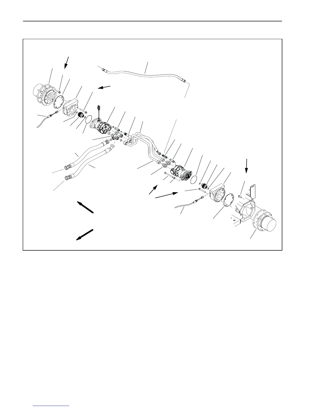
Figure 17
1. Planetary assembly
2. Flange head screw (6 per drive)
3. Gasket (2)
4. O−ring (2)
5. Brake assembly
6. Flange head screw (4 per brake)
7. Retaining ring (4)
8. Splined brake shaft (2)
9. Flat washer (4)
10. Cap screw (2 per motor)
11. Straight hydraulic fitting (2)
12. Hydraulic adapter (2)
13. Hydraulic tee fitting
14. Hydraulic tube assembly
15. Hydraulic tube assembly
16. Hydraulic hose
17. Hydraulic tee fitting (2)
18. RH wheel motor (with speed sensor
19. Hydraulic hose (to reservoir)
20. Hydraulic hose
(to lower pump fitting)
21. Hydraulic hose
(to upper pump fitting)
22. LH wheel motor
23. Brake cable (2)
FRONT
RIGHT
11
12
12
13
14
15
16
17
22
23
23
18
19
20
1
1
2
2
3
3
4
4
5
5
6
6
7
7
7
7
8
8
9
10
21
60 ft−lbs
(81 N−m)
to Piston
(Traction)
Pump
Lower
Port
to Piston
(Traction)
Pump
Upper
Port
Case
Drain
60 ft−lbs
(81 N−m)
60 ft−lbs
(81 N−m)
60 ft−lbs
(81 N−m)

 Loading...


