Multi Pro 5800Page 6 − 86Electrical System
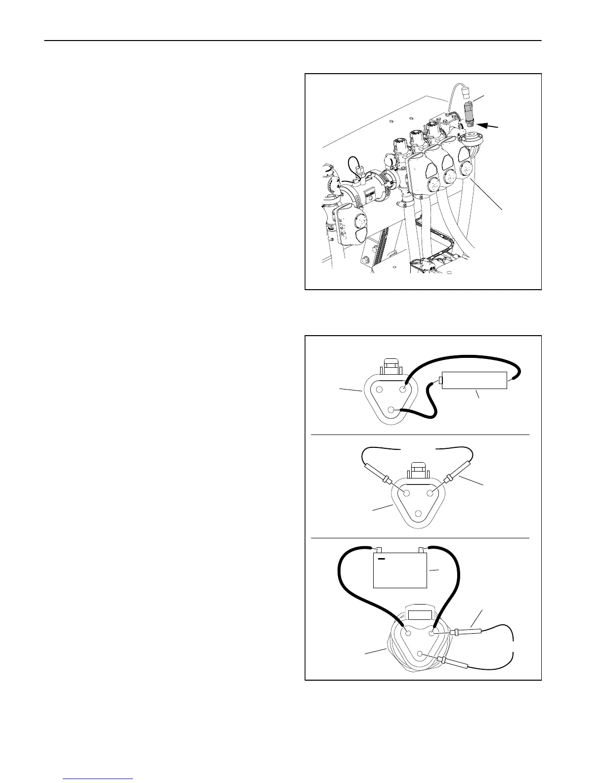
Pressure Transducer
In addition to an analog pressure gauge on the instru-
ment panel, the spray system includes a pressure trans-
ducer to provide spray system pressure information to
the InfoCenter Display. The pressure transducer is lo-
cated on the end of the Spray Manifold (Fig. 129).
Testing
1. Park machine on a level surface, stop engine and en-
gage parking brake.
2. Disconnect machine wire harness from the pressure
transducer.
3. Test the machine wire harness to the pressure trans-
ducer:
A. Set the ignition switch to the RUN/PREHEAT po-
sition.
B. To simulate a functioning pressure transducer,
connect a 1.5V dry cell battery across the signal (+)
pin C and ground (−) pin B of the machine wire har-
ness connector (Fig. 130A). A fully charged battery
should produce approximately an 80 psi (5.5 bar)
reading on the InfoCenter Display.
C. Use a multimeter set to DC voltage and check for
12 VDC across the supply (+) pin A and ground (−)
pin B of the machine wire harness (Fig. 130B).
D. Turn the ignition switch to OFF.
4. Test pressure transducer:
E. Connect a 12 VDC power supply to the supply (+)
pin A and ground (−) pin B of the sensor connector
(Fig. 130B).
F. Connect a multimeter set to DC voltage to the sig-
nal (+) pin C and ground (−) pin B of the sensor con-
nector (Fig. 130C). A small amount of voltage should
be present 0.5 VDC on the multimeter display.
5. Replace pressure transducer if necessary. Apply
thread sealant to transducer threads prior to installation.
6. Connect the wire harness to the pressure transducer
after testing is complete.
1. Spray manifold 2. Pressure transducer
Figure 129
1
2
THREAD
SEALANT
1. Machine wire harness
connector
2. 1.5 V dry cell battery
3. Multimeter probe
4. Pressure transducer
5. 12 VDC power supply
Figure 130
A
C
B
B
C
A
1
12 VDC
0.5 VDC
+
B
A
12 VDC
A
C
B
1
1.5 V DRY CELL
C
3
2
3
4
5

 Loading...


