Multi Pro 5800 Page 6 − 47 Electrical System
Toro Electronic Controller (TEC)
Multi Pro 5800 machines with serial numbers above
316000000 use a Toro Electronic Controller
(TEC−5002) to control electrical system operation. The
TEC is a microcontroller that monitors the condition of
various switches and sensors (inputs). The controller
then directs electrical power to control appropriate ma-
chine functions (outputs) based on the state of one or
more inputs.
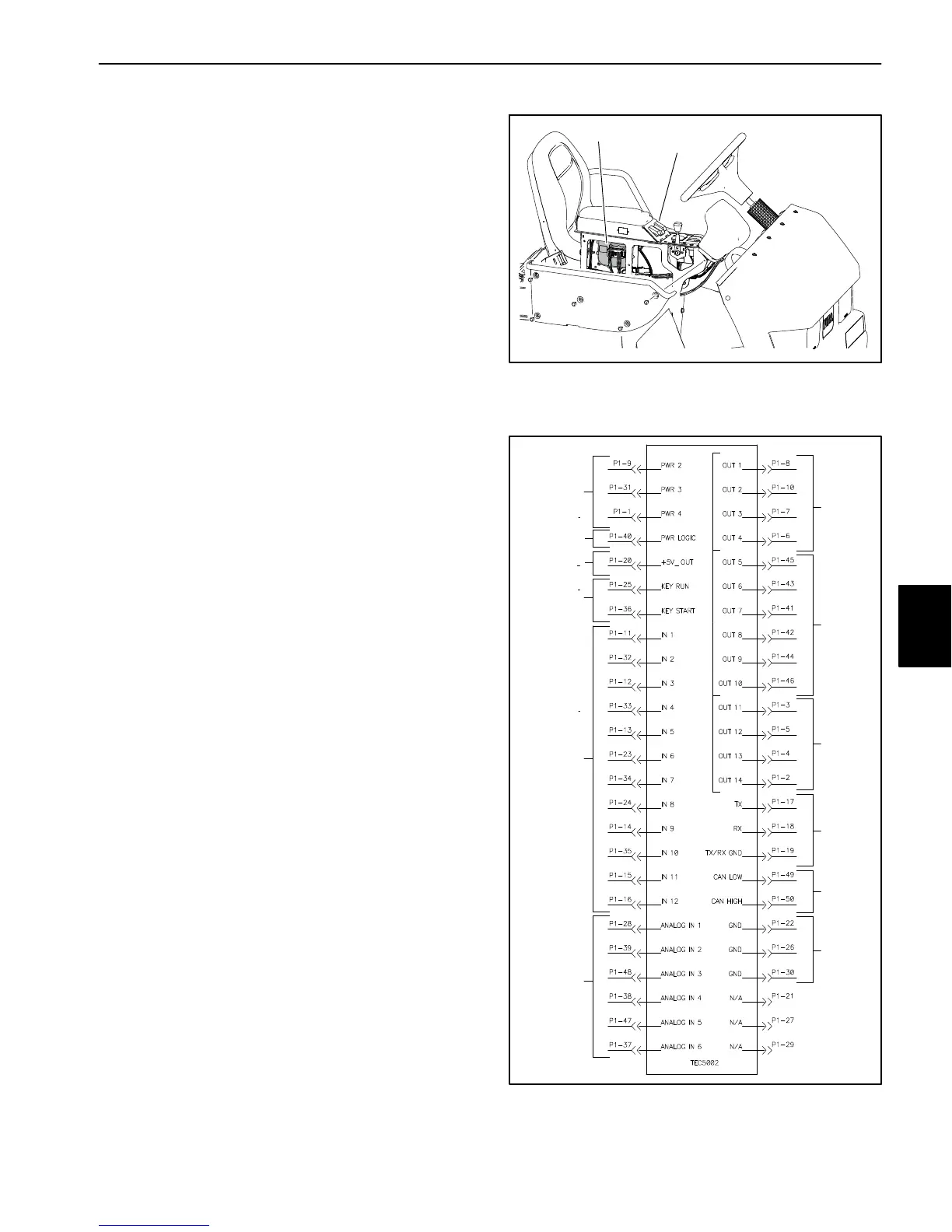
The controller is attached to the left side of the control
console frame (Fig. 53). Logic power is provided to the
controller as long as the battery cables are connected to
the battery. A 2 amp fuse provides circuit protection for
this logic power to the controller.
The TEC−5002 monitors the states of the following com-
ponents:
Traction Unit Inputs: ignition switch, seat switch,
brake pedal switch, neutral switch, spray pump
switch and optional clean rinse kit switches (if
equipped).
Manual Spray System Inputs: boom switches (mas-
ter, left, right and center spray), agitation switch,
speed sensor and manual rate control switch.
ExcelaRate Spray System Inputs (in addition to the
manual spray system inputs): spray mode switch,
spray system flow meter and spray pressure trans-
ducer.
The TEC−5002 controls electrical output to the following
components:
Traction Unit Outputs (diesel engines): engine start
relay, glow controller, run/stop solenoid hold coil, au-
dible alarm and brake lights.
Traction Unit Outputs (gasoline engines): engine
ECU, audible alarm and brake lights (opt.).
Spray System Outputs: spray pump control sole-
noid, boom spray valves, agitation valve and the
clean rinse kit pump relay (opt.).
The InfoCenter display should be used to check inputs
and outputs of the TEC. Information on using the In-
foCenter is included in the InfoCenter Display section of
this chapter.
The connection terminal functions for the TEC are
shown (Fig. 54). Note that electrical power for controller
outputs is provided through three (3) connector termin-
als (PWR 2, PWR 3 and PWR 4) each protected with a
7.5 amp fuse. A fifty (50) pin wire harness connector at-
taches to the controller. The layout of the wire harness
connector that plugs into the TEC is shown (Fig. 55).
1. Control console 2. Toro Electronic
Controller (TEC)
Figure 53
1
2
Figure 54
12V POWER
(7.5A FUSES)
12V LOGIC
IGNITION
SWITCH
INPUTS
DIGITAL
INPUTS
(OPEN/
ANALOG
INPUTS
POWER
(2 AMP FUSE)
COMM
PORT
CAN BUS
CLOSED)
OUTPUTS
(PWR 2)
GROUND
(VARIABLE)
OUTPUTS
(PWR 3)
OUTPUTS
(PWR 4)
VOLTAGE
OUT
Electrical
System

 Loading...


