Multi Pro 5800Page 6 − 52Electrical System
Spray−Mode Switch (ExcelaRate Spray Systems Only)
The spray−mode switch is located on the left side of the
instrument panel (Fig. 61) and is used to select between
Auto and Manual spray mode control.
Testing
1. Park machine on a level surface, stop engine and en-
gage parking brake. Remove key from ignition switch.
2. Locate the switch to be tested and disconnect the
wire harness electrical connector from the switch.
3. With the use of a multimeter (ohms setting), the
switch functions may be tested to determine whether
continuity exists between the various terminals for each
position. The switch terminals are marked as shown
(Fig. 66) and the circuitry of the spray−mode switch is
shown in the chart (Fig. 64). Verify continuity between
switch terminals.
SWITCH
POSITION
CLOSED
TERMINALS
OPEN
TERMINALS
AUTO 2 + 1, 5 + 4 2 + 3, 5 + 6
MANUAL 2 + 3, 5 + 6 2 + 1, 5 + 4
Figure 64
4. Replace switch if necessary.
5. If the switch tests correctly and a circuit problem still
exists, check the wire harnesses (see Electrical Sche-
matics and Wire Harness Drawings and Diagrams in
Chapter 11 − Foldout Drawings in this manual).
6. Connect the wire harness connector to the switch af-
ter testing is complete.
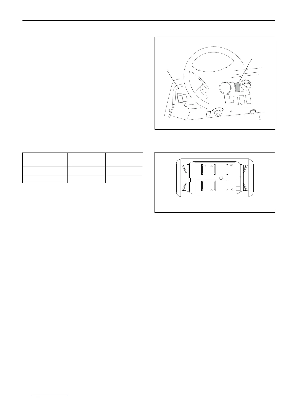
1. Instrument panel 2. Spray−mode switch
Figure 65
1
2
Figure 66
BACK OF SWITCH
NOTE: Spray−mode switch terminals 1, 4, 5 and 6 are
not used on Multi Pro 5800 machines.

 Loading...


