Multi Pro 5800Page 6 − 44Electrical System
Fuses
The fuse blocks are located under the operator seat on
the left seat base panel. Machines with Kubota gasoline
engines also have a number of fuses located in an en-
gine power center located on top of the engine toward
the rear and a Maxi−fuse located in the Kubota engine
wire harness (see Engine Fuses (Kubota Gasoline En-
gine) in this chapter).
Fuse Identification and Function
NOTE: Fuses for optional equipment appear at end of
the following Fuse Identification and Function list.
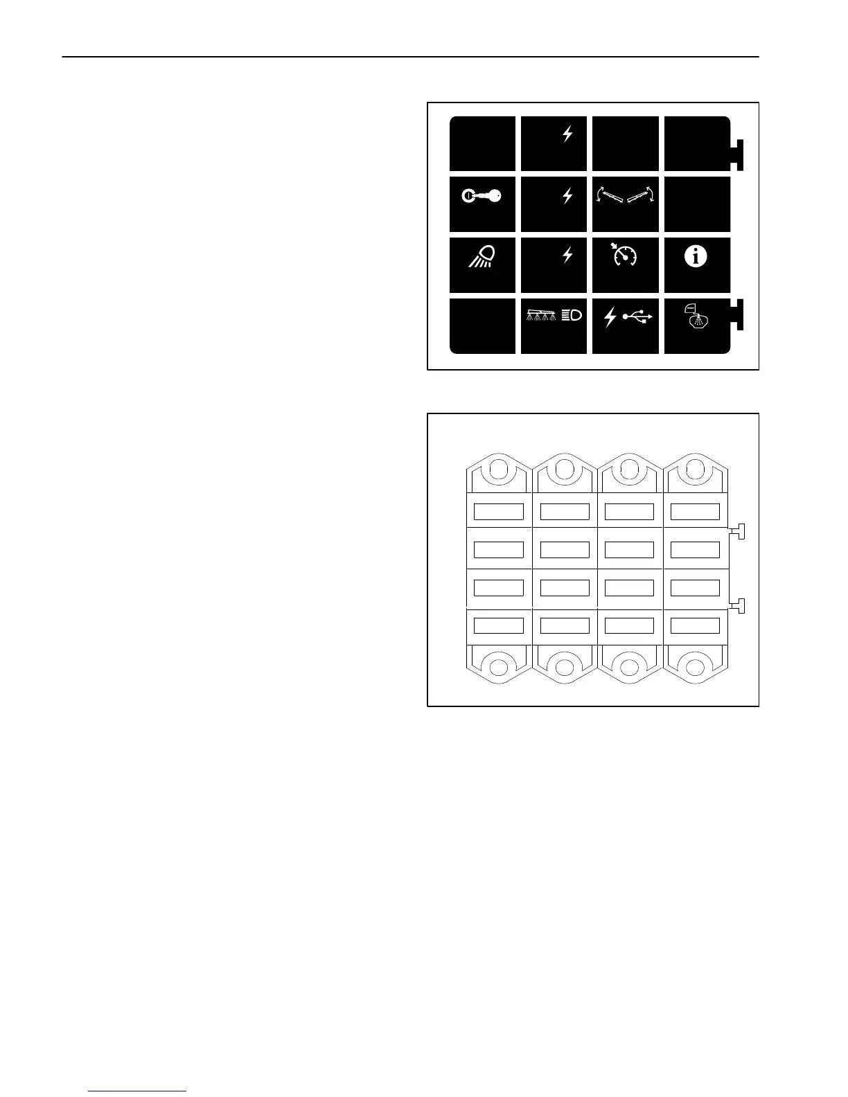
Use the fuse decal (Fig. 49) and fuse block (Fig. 50) to
identify each individual fuse and its correct amperage.
The fuses have the following functions:
FB1 1−2 and 3−4 available to protect switched power
circuits for optional kits.
FB1 5−6 (1 amp) protects InfoCenter power circuit.
FB1 7−8 (40 amp) protects rinse pump circuit for option-
al tank clean rinse kit.
FB2 1−2 (10 amp) protects the agitation valve, right
spray valve, center spray valve, and left spray valve
close signal circuits.
FB2 3−4 (10 amp) protects boom lift circuits.
FB2 5−6 (10 amp) protects speed control circuit.
FB2 7−8 (15 amp) protects power point circuit.
FB3 1−2 (7.5 amp) protects TEC output power supply
for engine start relay, hold coil of run/stop solenoid for
diesel engines or fuel pump relay for gasoline engines,
and the left and center boom valve open signal. Fault
code #2 should be displayed on the InfoCenter Display
if this fuse is faulty.
FB3 3−4 (7.5 amp) protects TEC output power supply
for the audible alarm and the spray pump control mani-
fold solenoid valve. Fault code #2 should be displayed
on the InfoCenter Display if this fuse is faulty.
FB3 5−6 (7.5 amp) protects TEC output power supply
for the right boom valve and agitation valve open signal,
rinse pump relay for optional tank clean rinse kit and
brake lights. Fault code #2 should be displayed on the
InfoCenter Display if this fuse is faulty.
FB3 7−8 (30 amp) protects headlight, fuel gauge, op-
tional MyTurft hour meter, turn signals, ground speed
sensor, flow meter, pressure transducer, and spray
pump switch and agitation switch indicator light circuits.
7.5A
TEC
TEC
LOGIC
2A 10A
7.5A15A 10A
7.5A15A 10A 1A
30A 15A
40A
TEC
TEC
Figure 49
Figure 50
10A
10A
15A
1A
10A
7.5A
30A
7.5A
15A
2A
FB1FB2FB3FB4
1−2
3−4
5−6
7−8
40A
7.5A15A
FB4 1−2 (2 amp) protects logic power circuit to the TEC.
FB4 3−4 (15 amp) protects main power relay circuit.
FB4 3−4 (15 amp) protects hazard flasher circuit.
FB4 7−8 available to protect maintained power circuits
for optional kits
Optional electric hose reel (40 amp) protects the op-
tional hose reel motor circuit. The fuse is located in the
hose reel control box.
Optional homologation (road light) kit (5 amp − 2)
protects the optional rear position light circuits. The fus-
es are located in the homologation kit wire harness near
the rear light assemblies.

 Loading...


