Multi Pro 5800Page 10 − 20Ultra Sonic Boom Kit (Optional)
Ultra Sonic Boom Switch
The sonic boom switch is used as an input for the Toro
electronic controller (TEC) to activate the Ultra Sonic
Boom System. This switch has three (3) positions: auto-
matic system off, automatic system on and a third posi-
tion to allow the operator to operate the booms in
manual mode. The sonic boom switch is located on the
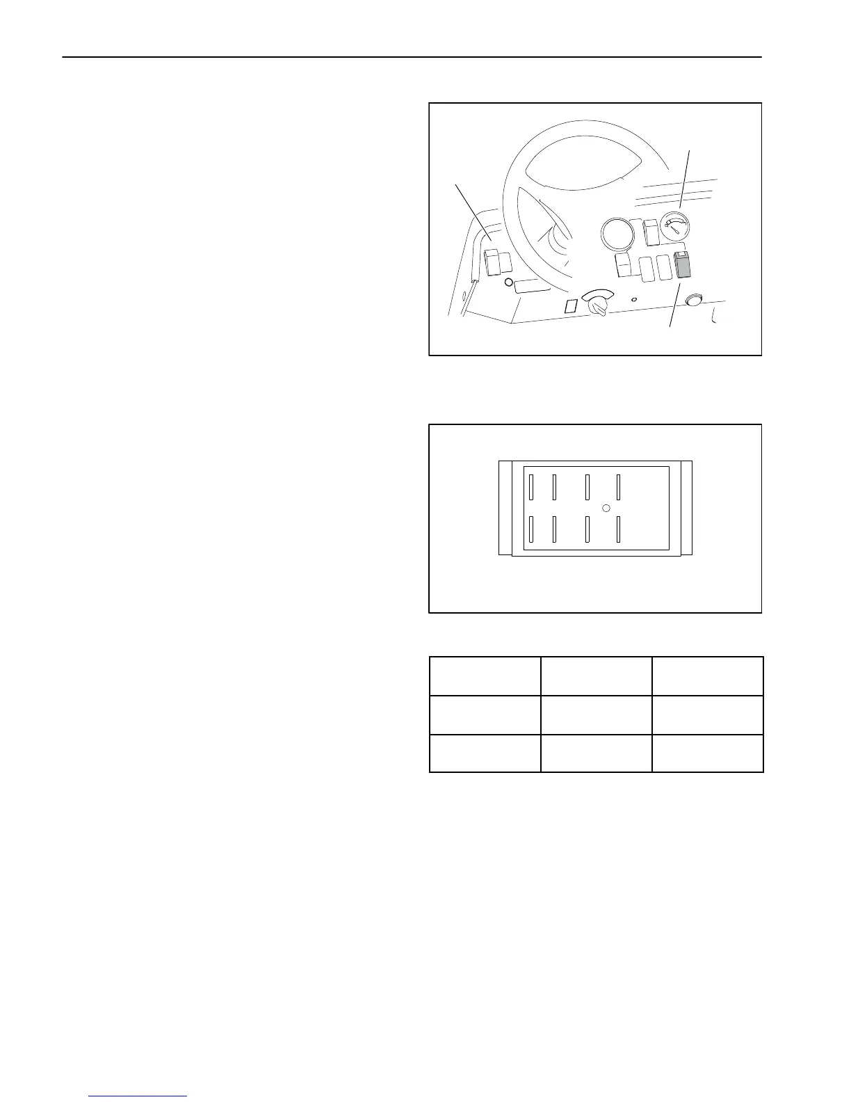
dash panel (Fig. 12).
If the sonic boom switch is in the automatic position, the
sonic sensors will be activated to allow automatic move-
ment of the booms. The tips of the booms will remain at
a constant distance from the ground. The boom lift
switches can be used to raise/lower the booms when the
sonic boom switch is in the automatic position. The light
in the switch should be illuminated when the switch is in
the automatic position.
If the sonic boom switch is in the manual position, the
sonic sensors are disabled and the boom lift switches
are used to raise/lower the booms.
Testing
The ultra sonic boom switch and its circuit wiring can be
tested as a TEC input (contact an Authorized Toro Dis-
tributor). If testing determines that the switch and circuit
wiring are not functioning correctly, or if Toro diagnostic
equipment is not available, proceed with the following
test procedure:
1. Park vehicle on a level surface, stop engine, engage
parking brake and remove key from ignition switch.
2. Disconnect wire harness electrical connector from
the sonic boom switch on the dash.
3. The switch terminals are marked as shown in Figure
13. The circuit logic of the sonic boom switch is shown
in the chart to the right. With the use of a multimeter
(ohms setting), the switch functions may be tested to de-
termine whether continuity exists between the various
terminals for each switch position. Verify continuity be-
tween switch terminals. Replace switch if testing identi-
fies a faulty switch.
4. To test switch light, apply 12 VDC to terminal 8 (+)
and ground terminal 7 (−). The light should illuminate.
5. If the sonic boom switch tests correctly and circuit
problem still exists, check wire harness.
6. After testing is completed, connect wire harness
connector to the sonic boom switch.
1
2
3
1. Instrument panel
2. Ultra sonic boom switch
3. Fuel gauge
Figure 12
Figure 13
BACK OF SWITCH
46
1
5
82
7
3
SWITCH
POSITION
CLOSED
CIRCUITS
OPEN
CIRCUITS
MANUAL 2 + 3
5 + 6
2 + 1
5 + 4
AUTOMATIC 2 + 1
5 + 4
2 + 3
5 + 6

 Loading...


