Multi Pro 5800Page 7 − 48ExcelaRate Spray System
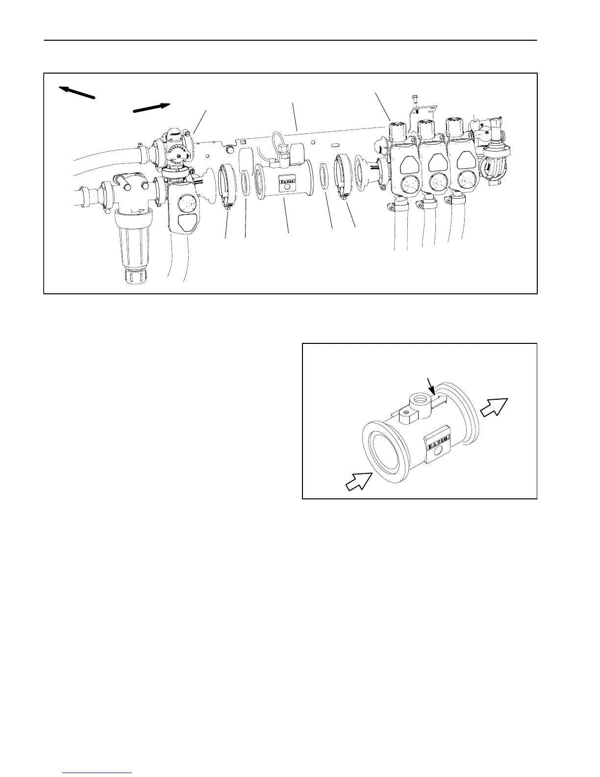
Flow Meter
1. Flow meter
2. Agitation valve assembly
3. Boom section valve assembly
4. Clamp (2)
5. Gasket (2)
6. Valve mount
Figure 46
FRONT
RIGHT
1
3
2
4
4
5
5
6
The flow meter (item 3) provides an input to the Toro
Electronic Controller (TEC) regarding the spray system
flow that is available to the boom spray valves. If the flow
meter is being replaced, calibrate the flow meter after in-
stallation (see Flow Calibration in the machine Opera-
tor’s Manual or Software Guide).
IMPORTANT: Make sure to remove and neutralize
chemicals from spray components before disas-
sembly. Wear protective clothing, chemical resist-
ant gloves and eye protection during repair.
Removal (Fig. 46)
1. Park machine on a level surface, stop spray pump,
stop engine and engage parking brake. Remove key
from ignition switch.
2. Disconnect wire harness connector from flow meter.
IMPORTANT: Note the direction of the arrow on top
of flow meter (Fig. 47). The arrow should point to-
ward the boom section valve assembly.
3. Remove the boom section valve assembly or agita-
tion valve assembly from machine (see Spray Control
Manifold Assembly in this chapter).
4. Support flow meter and loosen clamp that secures
flow meter to remaining manifold assembly.
5. Remove flow meter and discard gaskets (item 5).
See Flow Meter Service in this chapter for additional in-
formation.
Figure 47
NOTE ARROW
DIRECTION
TO BOOM
SECTION
VALVE
FROM
AGITATION
VALVE
ASSEMBLY
Installation (Fig. 46)
NOTE: Replace, do not reuse gaskets and O−rings.
Coat O−rings and gaskets with vegetable oil or silicone
grease before installation to reduce damage during as-
sembly.
1. Make sure that arrow on flow meter body is pointing
toward the boom section valve assembly (Fig. 47) and
secure flow meter to valve assembly on machine with a
clamp and a new gasket.
2. Connect wire harness connector to flow meter.
3. Operate spray system and check for leaks. Repair all
leaks before returning the sprayer to service.

 Loading...


