Multi Pro 5800 Page 6 − 65 Electrical System
Traction Speed Sensor
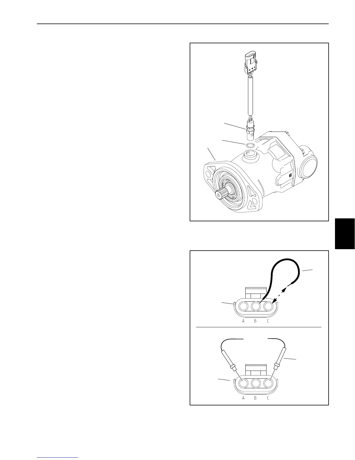
The traction speed sensor is attached to the right side
rear wheel motor (Fig. 95). The sensor provides ground
speed information to the InfoCenter display. Information
from the ground speed sensor is used by the various
spray control systems to control application rate. The
sensor uses a magnetically based, Hall Effect integrated
circuit. As the piston group in the wheel motor turns, the
sensor accurately senses the movement of the pistons
passing the sensor. The relationship of the sensor to the
rotating piston group is critical as the sensor is designed
to read movement in one direction and must be perpen-
dicular to the piston group within three (3) degrees. The
sensor red connector wire (pin A) is the positive lead, the
black wire (pin C) is the ground lead and the white wire
(pin B) is the signal output.
Testing
1. Park machine on a level surface, stop engine and en-
gage parking brake.
2. Disconnect machine wire harness from speed sen-
sor.
3. Test the machine wire harness to the speed sensor:
A. Set the ignition switch to the RUN/PREHEAT po-
sition.
B. Connect a jumper wire across the ground (−) pin
C and the signal (+) pin B (Fig. 96A). Have an assis-
tant watch the InfoCenter Display as you open and
close the connection across the pins multiple times.
Vehicle speed readings other than 00.0 should ap-
pear on the InfoCenter Display.
C. Remove the jumper wire.
D. Use a multimeter set to DC voltage and check for
12 VDC across the supply (+) pin A and ground (−)
pin C of the machine wire harness (Fig. 96B).
E. Turn the ignition switch to OFF.
4. Test the speed sensor:
A sensor test harness is required to quickly check sen-
sor operation without removing the sensor from the
wheel motor.
NOTE: Instructions for fabricating and using a traction
sensor test harness can be found in the Special Tools
section of this chapter or contact your Authorized Toro
Distributor for assistance.
1. RH wheel motor
2. Speed sensor
3. O−ring
Figure 95
1
2
3
Figure 96
1. Machine wire harness
connector
2. Jumper wire
3. Multimeter probe (typ.)
1
3
12 VDC
A
B
2
1
Electrical
System

 Loading...


