Multi Pro 5800 ChassisPage 9 − 5
Tie Rod
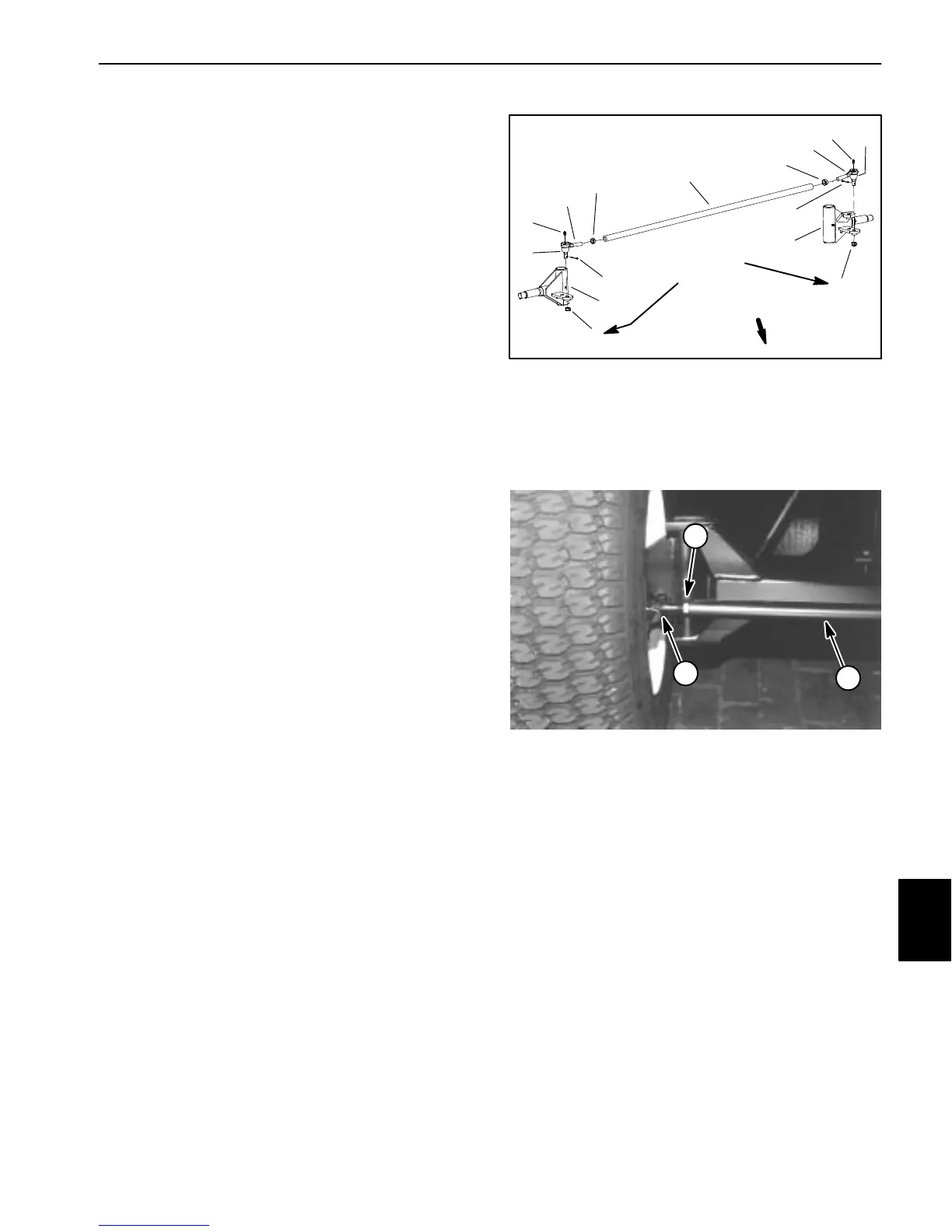
Removal (Fig. 3)
1. Park machine on a level surface, stop engine, en-
gage parking brake and remove key from the ignition
switch.
NOTE: Left side tie rod end has a left hand threaded
jam nut.
2. Loosen jam nut on tie rod end.
3. Remove cotter pin and castle nut that secure tie rod
end to spindle.
4. Use a suitable puller (pickle fork) to separate tie rod
end from spindle.
5. When removing tie rod end from tie rod, count the
number of revolutions it takes to remove so new tie rod
end can be installed with minimal change to front wheel
toe−in.
Installation (Fig. 3)
1. Install dust boot on new tie rod end.
2. Thread tie rod end into tie rod the same number of
revolutions as the old tie rod end took to remove.
3. Install grease fitting into tie rod end.
4. Insert tie rod end shaft into spindle and secure with
castle nut. Torque castle nut from 20 to 25 ft−lb (27 to
33 N−m). If necessary, nut can be tightened slightly fur-
ther to align cotter pin position in spindle and nut. Install
cotter pin.
5. Grease tie rod end.
6. Check front wheel toe−in and adjust if needed. Front
wheel toe−in should be from 1/8 to 1/4 inch (3.2 to 6.4
mm).
7. Adjust steering stop bolt on each spindle so that at
full turn, there is a gap from 1/16” to 1/8” (1.6 to 3.2 mm)
between the head of the stop bolt and the axle stop lug.
8. Verify that there is at least a 1/16” (1.6 mm) gap be-
tween the tie rod and front axle when turning full right to
left.
9. After assembly is complete, make sure that steering
components do not contact hoses and/or electrical har-
ness wires.
1. Tie rod
2. Jam nut (RH thread)
3. RH tie rod end
4. Grease fitting
5. Castle nut
6. Cotter pin
7. Dust boot
8. RH spindle
9. LH spindle
10. LH tie rod end
11. Jam nut (LH thread)
Figure 3
6
9
1
5
10
2
3
4
7
8
4
5
6
7
11
FRONT
20 to 25 ft−lb
(27 to 33 N−m)
1. Tie rod
2. Jam nut
3. Tie rod end
Figure 4
2
1
3
Chassis

 Loading...


