Multi Pro 5800Page 6 − 54Electrical System
Application−Rate Switch
The application−rate (increase/decrease) switch is lo-
cated on the instrument panel directly below the pres-
sure gauge (Fig. 71). The application−rate switch is an
input to the TEC. When all necessary spray control con-
ditions are met, the TEC modifies the current applied to
the spray pump control manifold solenoid valve using a
PWM (pulse width modulation) signal. Pressing the
switch to the increase position increases the frequency
of the PWM signal to the valve coil which increases hy-
draulic flow to the spray pump motor. Moving the switch
to the decrease position reduces the frequency of the
PWM signal to the valve coil and results in less hydraulic
flow to the spray pump.
Testing
1. Park machine on a level surface, stop engine and en-
gage parking brake. Remove key from ignition switch.
2. Locate the switch to be tested ans disconnect the
wire harness electrical connector from the switch.
3. With the use of a multimeter (ohms setting), the
switch functions may be tested to determine whether
continuity exists between the various terminals for each
position. The switch terminals are marked as shown
(Fig. 72) and the circuitry of the application−rate switch
is shown in the chart (Fig. 70). Verify continuity between
switch terminals.
SWITCH
POSITION
CLOSED
TERMINALS
OPEN
TERMINALS
INCREASE 2 + 3, 5 + 6 2 + 1, 5 + 4
OFF NONE ALL
DECREASE 2 + 1, 5 + 4 2 + 3, 5 + 6
Figure 70
4. Replace switch if necessary.
5. If the switch tests correctly and a circuit problem still
exists, check the wire harnesses (see Electrical Sche-
matics and Wire Harness Drawings and Diagrams in
Chapter 11 − Foldout Drawings in this manual).
6. Connect the wire harness connector to the switch af-
ter testing is complete.
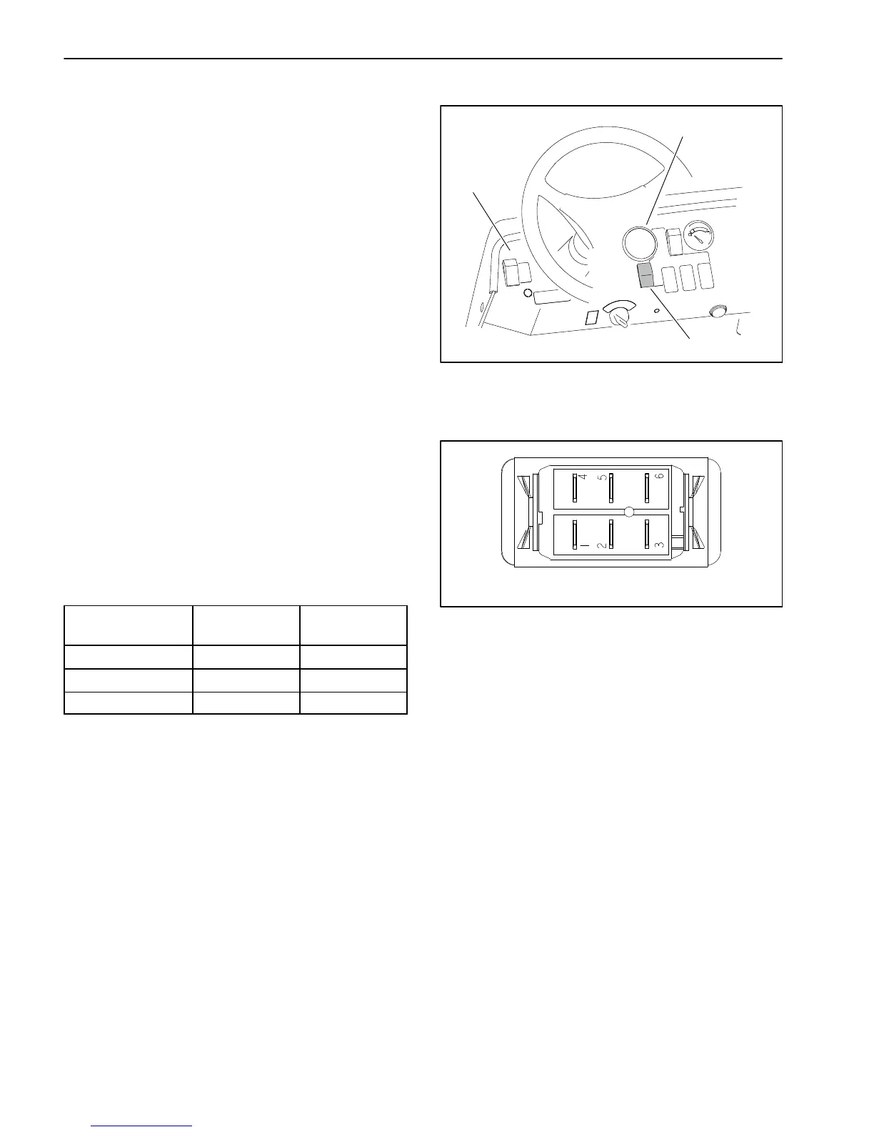
1. Instrument panel
2. Application−rate switch
3. Pressure gauge
Figure 71
1
2
3
Figure 72
BACK OF SWITCH
NOTE: Application−rate switch terminals 4, 5 and 6 are
not used on Multi Pro 5800 machines.

 Loading...


