Multi Pro 5800Page 6 − 66Electrical System
Hydraulic Valve Solenoid Coils
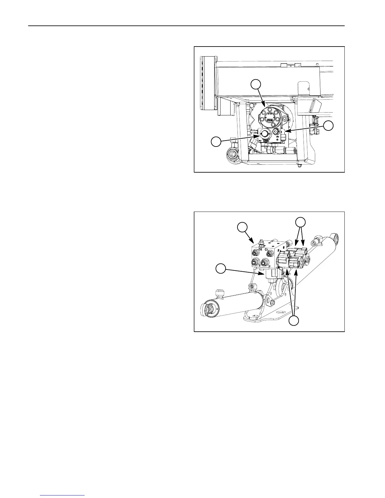
The Multi Pro 5800 hydraulic system uses several hy-
draulic solenoid valve coils for system control. The
spray pump control manifold includes one (1) single coil
solenoid valve (Fig. 97). The standard boom lift control
manifold includes one (1) single coil solenoid valve and
two (2) dual coil solenoid valves (Fig. 98). When the so-
lenoid coils are energized, hydraulic valve shift occurs
to control hydraulic flow. Testing of the coils can be done
with the coil installed on the hydraulic valve.
NOTE: The boom lift control manifold for machines with
an optional ultra sonic boom system includes two (2) sin-
gle coil solenoid valves and two (2) dual coil solenoid
valves. See Chapter 10 − Ultra Sonic Boom System in
this manual for additional information.
Testing
1. Park machine on a level surface, stop engine and en-
gage parking brake. Remove key from ignition switch.
2. Locate solenoid valve coil to be tested and discon-
nect wire harness connector from coil.
NOTE: Prior to taking small resistance readings with a
digital multimeter, short the meter test leads together.
The meter will display a small resistance value (usually
0.5 ohms or less). This resistance is due to the internal
resistance of the meter and test leads. Subtract this val-
ue from from the measured value of the solenoid you are
testing.
NOTE: Solenoid coil resistance should be measured
with solenoid at approximately 68F (20C). Resistance
may be slightly different than listed at different tempera-
tures. Typically, a failed solenoid coil will either be
shorted (very low or no resistance) or open (infinite re-
sistance).
3. Using a multimeter (ohms setting), measure resis-
tance between the two connector terminals on the sole-
noid valve coil. The resistance for the solenoid coils is
identified below:
A. The resistance of the solenoid coil on the spray
pump manifold should be 4.5 ohms.
B. The solenoid coils on the boom lift manifold are
identical. Resistance of these coils should be 8.8
ohms.
NOTE: Because the solenoid valve coils on the boom
lift control manifold are identical, they can be exchanged
to assist in troubleshooting. If the problem follows the
exchanged coil, an electrical problem likely exists with
the coil.
1. Spray pump drive motor
2. Spray pump control
manifold
3. Solenoid coil (PV)
Figure 97
3
1
2
1. Boom lift manifold
2. Solenoid coil (S1)
3. Solenoid coil (S2)
4. Solenoid coil (S3)
Figure 98
1
2
4
3
4. If solenoid coil resistance is incorrect, replace coil
(see Spray Pump Control Manifold Service or Boom Lift
Control Manifold Service in the Service and Repairs
section of Chapter 5 − Hydraulic System).
5. If the solenoid coil tests correctly and a circuit prob-
lem still exists, check wire harness (see Electrical Sche-
matic and Wire Harness Drawings in Chapter 11 −
Foldout Drawings in this manual).
6. After testing is completed, connect wire harness
electrical connector to the solenoid valve coil.