Multi Pro 5800Page 8 − 74GeoLink Spray System
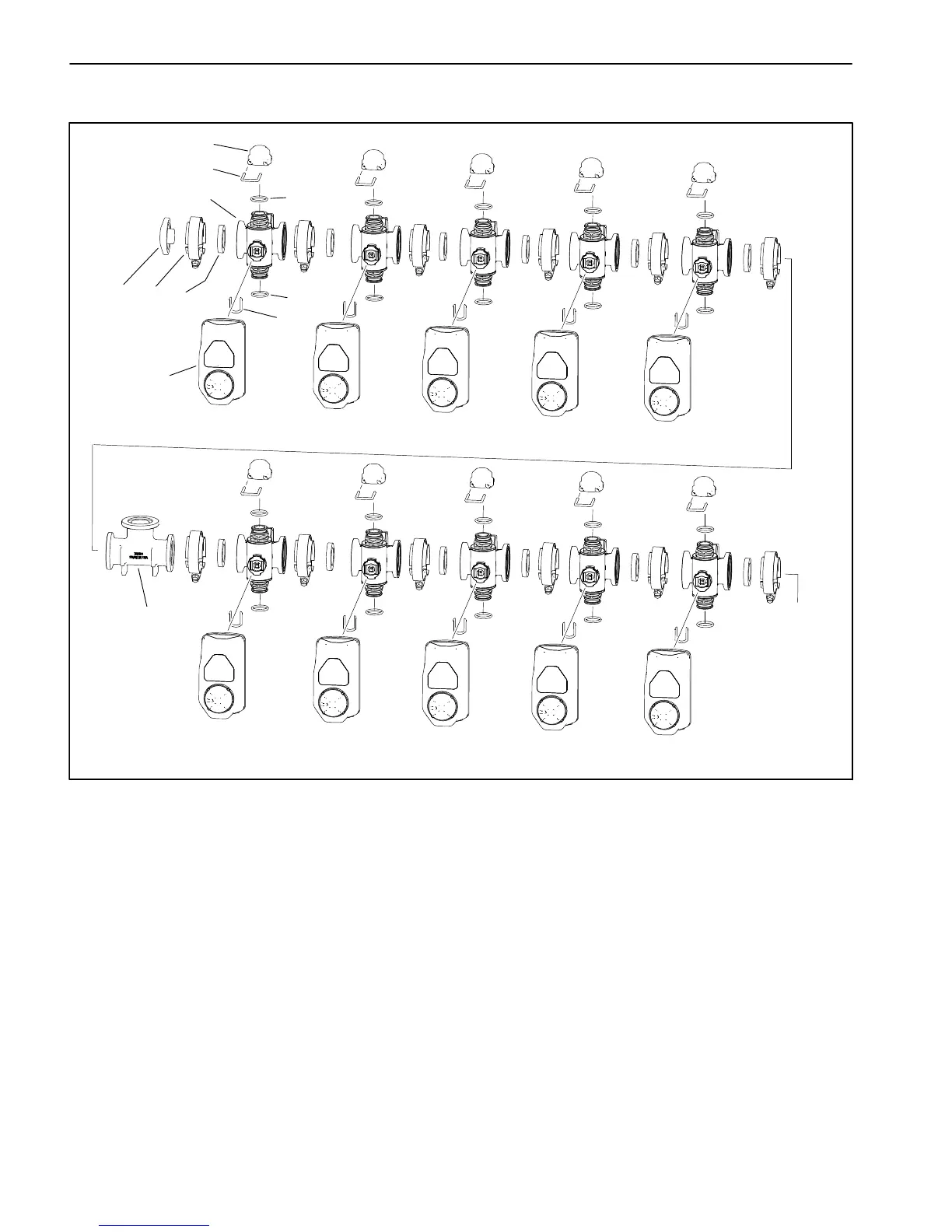
Nozzle Valve Assembly
1. Valve actuator (10)
2. Fork (10)
3. Nozzle valve (10)
4. Gasket (12)
5. Clamp (12)
6. O−ring (20)
7. Port cap
8. Fork (10)
9. Cap (10)
10. Tee
Figure 79
CAP
OR
CONNECT
TO
ACCESSORY
NOZZLE
VALVE 1
NOZZLE
VALVE 2
NOZZLE
VALVE 9
NOZZLE
VALVE 10
NOZZLE
VALVE 11
NOZZLE
VALVE 12
NOZZLE
VALVE 3
NOZZLE
VALVE 4
NOZZLE
VALVE 5 AND 6
NOZZLE
VALVE 7 AND 8
1
2
3
4
5
6
6
7
8
9
10
The nozzle valve assembly includes the ten (10) nozzle
valves that control the twelve (12) spray nozzles. The
nozzles and valves are referred to by number from right
to left across the back of the machine. Nozzles number
5 and 6 are controlled by a single valve, and nozzles
number 7 and 8 are controlled by a single valve.
IMPORTANT: Each valve actuator has an internal
circuit breaker to protect the actuator motor. The
circuit breaker should reset in 20 seconds after
power to the actuator is removed.