Multi Pro 5800 Page 6 − 69 Electrical System
Glow Plug Controller (Diesel Engines Only)
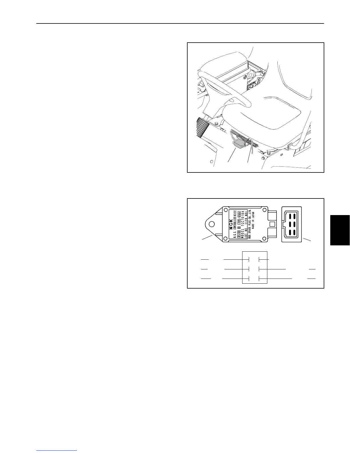
The engine electrical system in Multi Pro 5800 ma-
chines with diesel engines includes a Kubota glow plug
controller. The glow plug controller is energized by the
TEC. The glow plug controller is attached to the front
seat base panel under the operator seat (Fig. 103).
Controller Operation
1. When the ignition switch is placed in the RUN/PRE-
HEAT position, the glow plug controller energizes the
glow plugs and illuminates the glow plug indicator light
for approximately six (6) seconds.
2. When the ignition switch is held in the START posi-
tion, the glow plugs will energize while the switch is held
in START and the glow plug indicator light will not be illu-
minated.
3. When the ignition switch is released from START to
RUN/PREHEAT, the glow plugs will de−energize and
the glow plug indicator light will remain off.
Testing
1. Park machine on a level surface, stop engine and en-
gage parking brake.
2. Raise the operator seat and disconnect wire harness
connector from the fuel run/stop solenoid to prevent the
engine from starting.
3. Make sure there is power from the battery at the igni-
tion switch.
4. Place ignition switch in the RUN/PREHEAT position
and verify the following conditions are present:
A. Glow plug indicator light is illuminated.
B. Glow relay is energized.
C. Glow plugs are energized.
D. Glow plug indicator light goes out and glow plugs
de−energize after approximately six (6) seconds.
5. Place ignition switch in the START position. Verify
the following while the ignition switch is in the START
position:
A. Glow plug indicator light is out.
B. Glow relay is energized.
C. Glow plugs are energized.
D. Power exists at terminal 1 of the glow controller.
NOTE: If there is no power to terminal 1 of the glow con-
troller, verify continuity of the circuitry from the ignition
switch to the controller and perform Step 4 again (see
Chapter 11 − Foldout Drawings).
12
1. Operator seat 2. Glow plug controller
Figure 103
1. Glow controller top view 2. Controller end view
Figure 104
TEMP (not used)
GLOW
GROUND
VIOLET
+12V
LAMP
START
BLK/WHITE
BLACK
PINK
ORANGE
1
2
3
4
5
6
12
6. If any of the conditions in Step 3 are not met or power
to terminal 1 exists and any of the other conditions in
Step 4 are not met:
A. Verify continuity of the circuitry from the battery to
the glow relay and glow plugs (see Chapter 11 −
Foldout Drawings).
B. Verify continuity of the circuitry from the battery to
ignition switch, glow controller, glow plug indicator
light, glow relay and ground (see Chapter 11 − Fold-
out Drawings).
C. Repair or replace components as necessary.
7. When testing is complete, connect wire harness con-
nector to the fuel run/stop solenoid.
Electrical
System

 Loading...


